7.14 Encoder Emulation, position output
7.14.1 Incremental encoder output - A quad B (X1)
Fast incremental encoder interface. Select encoder function ROD (A Quad B) Encoder
(“Encoder Emulation” screen page). The servo amplifier calculates the motor shaft posi
-
tion from the cyclic- absolute signals of the resolver or encoder, generating incremen-
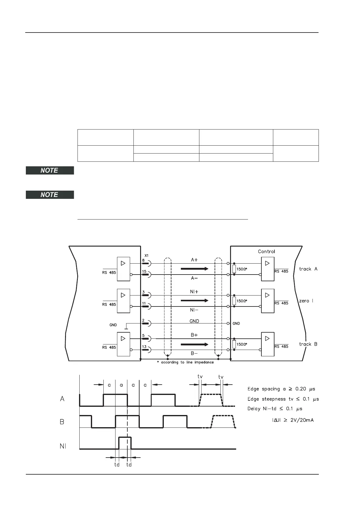
tal-encoder compatible pulses from this information. Pulse outputs on the SubD connec-
tor X1 are 2 signals, A and B, with 90° phase difference (i.e. in quadrature, hence the
alternative term “A quad B” output), with a zero pulse.
The resolution (before multiplication) can be set:
Encoder function
(ENCMODE)
Feedback system
(FBTYPE)
Resolution lines
(ENCOUT)
Zero pulse (NI)
9, ROD => X1
0, Resolver 32...4096 once per turn
(only at A=B=1)
>0, Encoder 256...524288 (2
8
…2
19
)
With built in safety card only binary resolutions up to 2
12
are possible.
Use the NI-OFFSET parameter to adjust + save the zero pulse position within one
mechanical turn. The drivers operate off an internal supply voltage.
The maximum permissible cable length is 100 meters.
Connections and signals for the incremental encoder interface :
Default count direction: UP when the motor shaft is rotating clockwise (looking at the
shaft's end)
96 S701x2-S724x2 Instructions Manual
Electrical installation 07/2014 Kollmorgen
S700

 Loading...


