5.9.7 Technical data and pinning
STO1-Enable and STO2-Enable Data
Input voltage
20V..30V
Input current
33mA – 40mA (Ieff)
Peak current
100mA (Is)
Response time (falling edge at STO input
until energy supply to motor is interrupted)
STO1: 1ms
STO2: 2ms
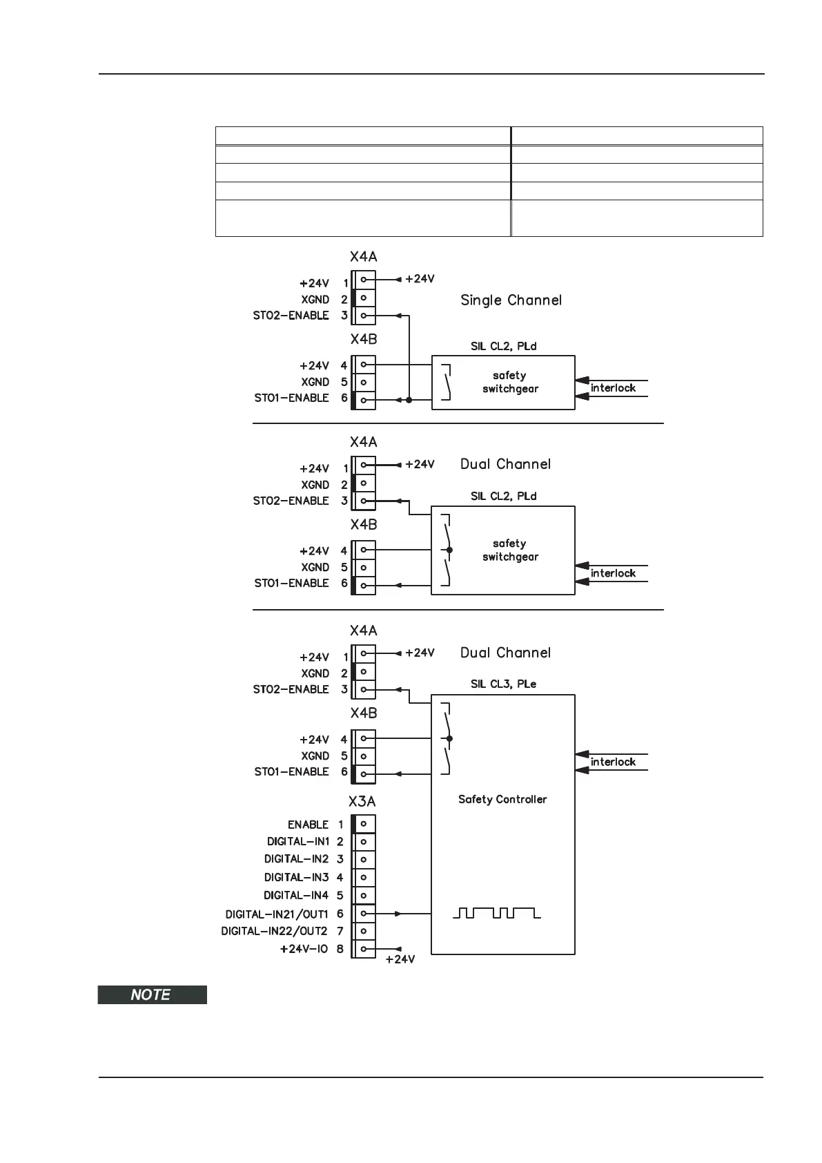
To achieve PLe / SIL CL3, the safe switching of the pulse inhibitor must be tested periodi
-
cally by analyzing the status signal from a safety control. Therefore the status must be lin
-
ked to one of the digital outputs DIGITAL-OUT1 or 2 (X3A/6 or X3A/7) with the ASCII
command OxMODE70.
S701x2-S724x2 Instructions Manual 43
Kollmorgen 07/2014 Technical description

 Loading...


