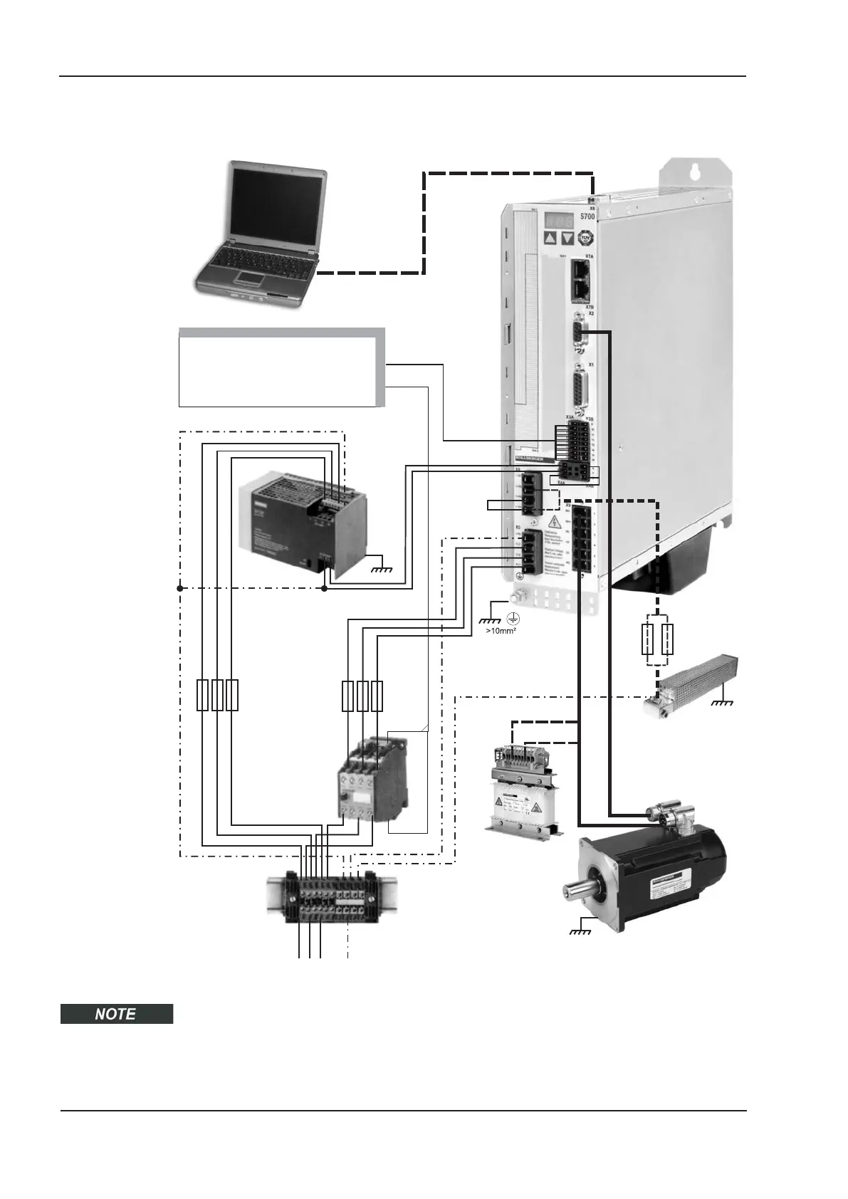
7.4 Components of a servo system
Cables drawn bold are shielded. Electrical ground is drawn with dash-dotted lines.
Optional devices are connected with dashed lines to the servo amplifier. The required
accessories are described in our accessories manual. STO function is deactivated in the
example.
62 S701x2-S724x2 Instructions Manual
Electrical installation 07/2014 Kollmorgen
24V PSU
Fuses
Drive cut-out
Terminals
Motor
S700
PC
Controls / PLC
Motor choke
(optional)
Brake resistor
(optional)

 Loading...


