7.9 DC bus link (X8)
Terminals X8/1 (-DC) and X8/2 (+RBe). Can be connected in parallel, whereby the brake
power is divided between all the amplifiers that are connected to the same DC bus link
circuit. With the optional Y-connector X8Y you can connect more than one S700 to the
DC bus or connect an additional external brake resistor.
In case of mains supply from the same mains (VBUSBAL must be identical with all devi-
ces on the same DC bus) these servo amplifiers may be connected by the DC bus link :
S701-724 with
HWR* < 2.00
S701-724 with
HWR* ³ 2.00
S748/S772 S300 AKD
S701-724 with HWR* < 2.00
yes no no no no
S701-724 with HWR* ³ 2.00
no yes no yes no
*HWR = Hardware Revision (check nameplate)
l
The servo amplifiers can be destroyed, if DC bus link voltages are different. Only ser-
vo amplifiers with mains supply from the same mains (identical mains supply voltage)
may be connected by the DC bus link.
l
The sum of the rated currents for all of the servo amplifiers connected in parallel to
an S700 must not exceed 48A.
l
Use 6mm², unshielded single cores with a max. length of 200mm; use 6mm² shielded
cables for longer lengths. In this case no fuse for line protection is required.
l
Servo amplifiers working generatively very often, should be placed beside amplifiers,
which need energy. That reduces current flow on longer distances.
Fusing information are explained in detail in the "Product Wiki", available at
www.wiki-kollmorgen.eu
, on the WIKI page "DC Bus link in parallel".
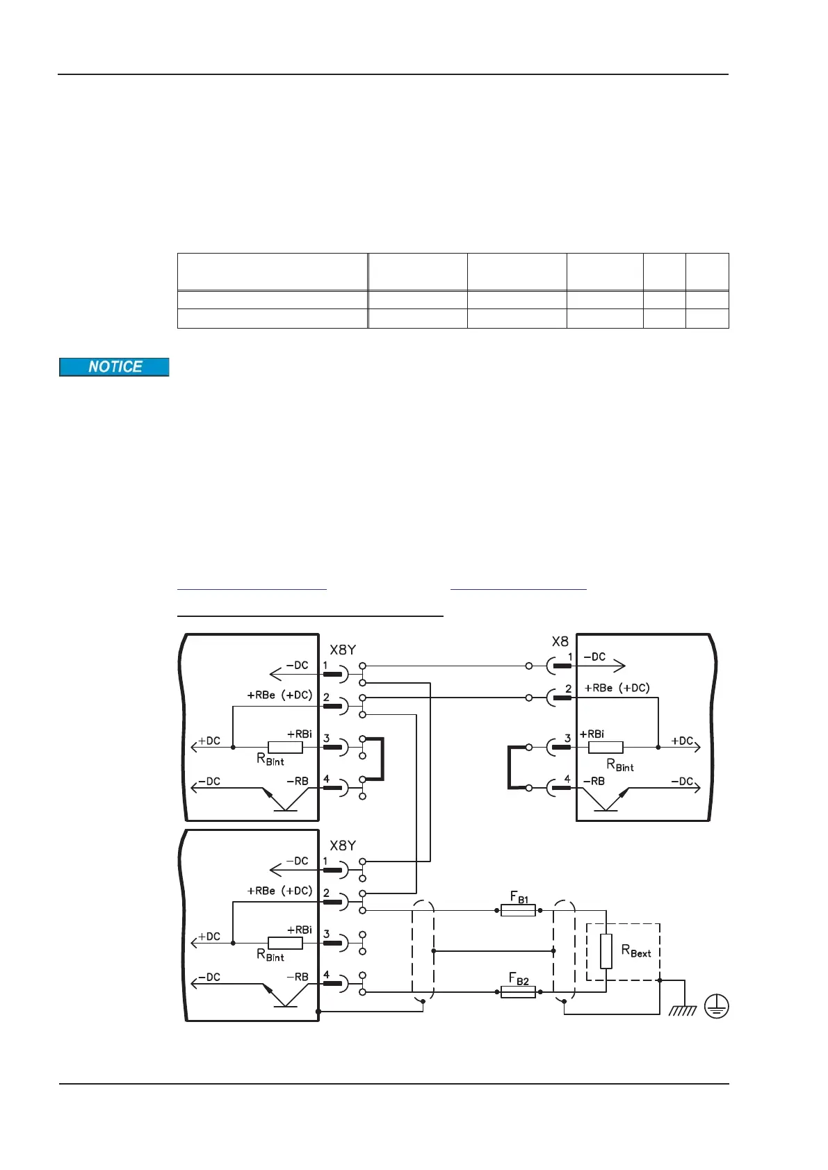
Wiring example with external brake resistor
70 S701x2-S724x2 Instructions Manual
Electrical installation 07/2014 Kollmorgen
S700
S700
S700

 Loading...


