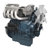
2. Measure
the
voltage
between the glow lead
terminal and the engine body with a circuit tester.
NOTE
• If the voltage
differs from the battery
voltage, the wiring harness or key switch is
damaged.
Voltage
Key switch at
“GLOW” (or “PRE-
HEAT”)
Approx. battery volt-
age
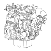
4.23 Checking glow plug continuity
Tools required
•
Circuit tester
1.
Remove the glow plug.
2.
Measure the resistance between the glow plug
terminal and the glow plug housing with a circuit
tester.
Resistance
Service specifi-
cation
Approx. 0.9 Ω
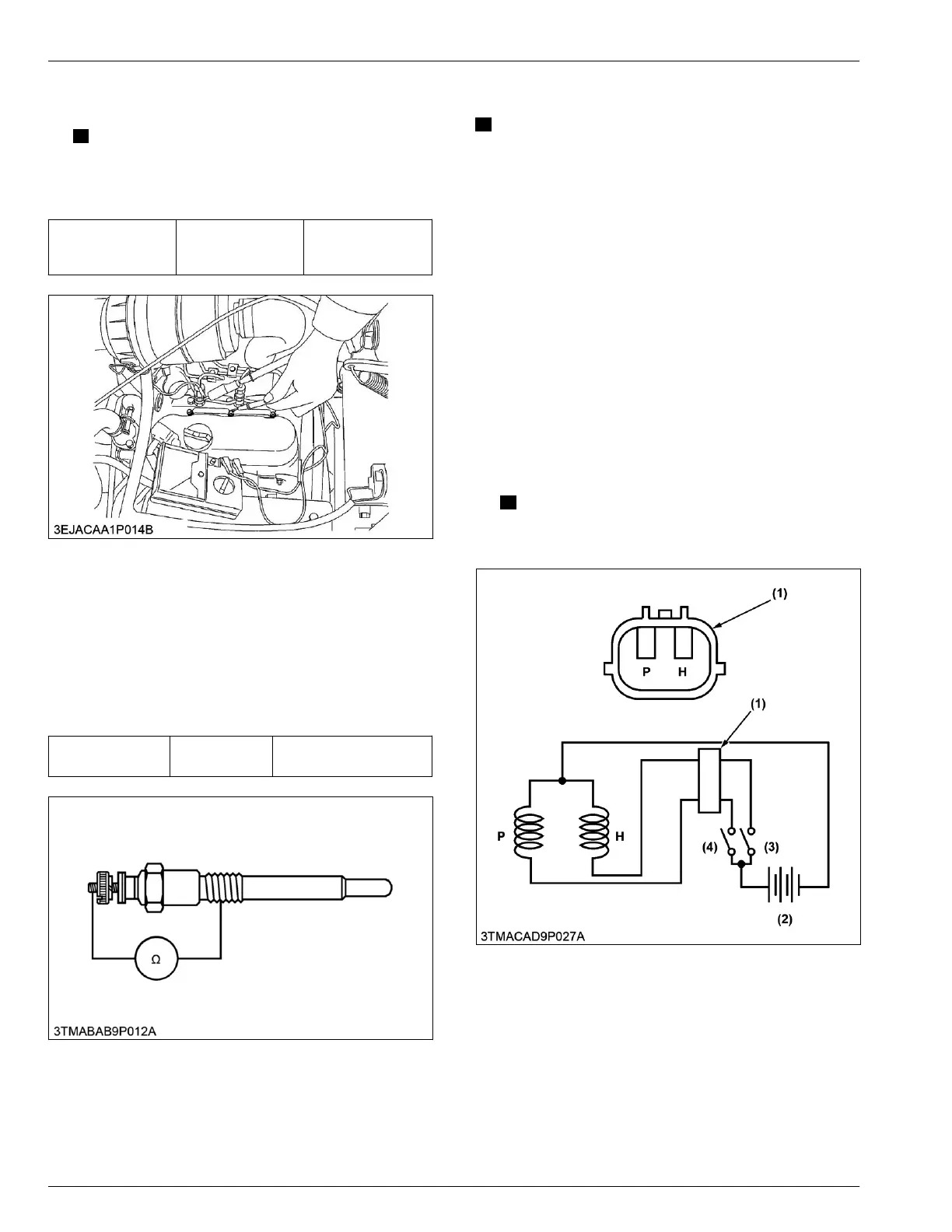
4.24 Checking engine stop solenoid
IMPORTANT
• Never apply the
current for pulling coil more
than 2 seconds when inspecting.
1. Remove the engine stop solenoid from the engine.
2. Connect the jumper
leads from the pulling coil P
terminal to the switch (4), and from switch (4) to the
battery positive terminal.
3. Connect the jumper leads from the holding coil H
terminal to the switch (3), and from switch (3) to the
battery positive terminal.
4. Connect the jumper leads from the engine stop
solenoid body to the battery negative terminal.
5. When switch (4) is turn on, the plunger pull into the
solenoid body and then turn off the switch (4), the
plunger comes out.
6. Turn on the switch (3) then turn on the switch (4),
the plunger pull into the solenoid body and it keep
in holding position after turn off the switch (4).
NOTE
• If the plunger
is not attracted, the engine
stop solenoid is damaged.
(1) Connector
(2) Battery
(3) Switch for holding coil
(4)
Switch for pulling coil
P: Terminal for pulling coil
H: Terminal for holding coil
4. ENGINE
SERVICING
4. Checking and adjusting
05-E4B SERIES,05-E4BG SERIES
 Loading...