Item
Dimension
× Pitch
N⋅m kgf⋅m lbf⋅ft
*Idle gear shaft screw M6 × 1.0 9.81 to 11.2 1.00 to 1.15 7.24 to 8.31
*Fan drive pulley screw M14 × 1.5 236 to 245 24.0 to 25.0 174 to 180
Bearing case cover mounting screw M6 × 1.0 10.8 to 12.2 1.10 to 1.25 7.96 to 9.04
Glow plug M8 × 1.0 7.9 to 14 0.80 to 1.5 5.8 to 10
Nozzle holder assembly M20 × 1.5 49 to 68 5.0 to 7.0 37 to 50
Nozzle holder - 35 to 39 3.5 to 4.0 26 to 28
Oil pressure switch PT 1/8 15 to 19 1.5 to 2.0 11 to 14
Injection pipe retaining nut M12 × 1.5 25 to 34 2.5 to 3.5 18 to 25
Overflow pipe retaining nut
(Serial No.: below BTZ999)
M12 × 1.5 20 to 24 2.0 to 2.5 15 to 18
Overflow pipe retaining nut
(Serial No.: above BU0001)
M12 × 1.5 35 to 39 3.5 to 4.0 26 to 28
Starter's B terminal nut M8 × 1.25 5.88 to 11.8
0.600 to
1.20
4.34 to 8.70
Alternator's pulley nut - 58.4 to 78.9 5.95 to 8.05 43.1 to 58.2
Drain plug with copper gasket M12 × 1.25 33 to 37 3.3 to 3.8 24 to 27
Drain plug with rubber coated gasket M22 × 1.5 45 to 53 4.5 to 5.5 33 to 39
4. Checking and adjusting
4.1 Checking compression pressure
of cylinder
NOTE
• Check the compression
pressure with the
specified valve clearance.
• Always use a fully charged battery for you do
this test.
• Variances in cylinder compression values must
be less than 10 %.
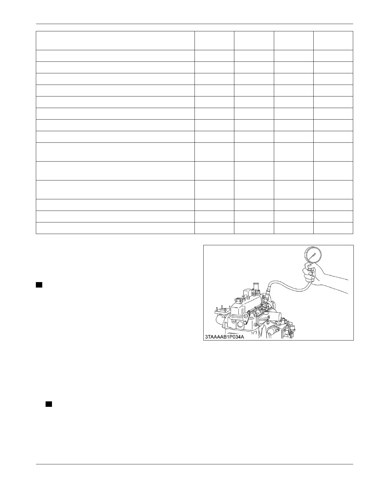
Tools required
• Compression tester
• Injector adapter
1. Warm-up the engine.
2. Stop the engine.
3. Remove the air cleaner and muffler.
4. Remove the all injection nozzles.
NOTE
• In
case
you
use compression tester adapter
for glow plug holes, remove the glow lead
and glow plugs.
5. Set a compression tester (Code No. 07909-30208)
with the adapter (Adapter H, code No.
07909-31231) to the nozzle hole.
6. After
making sure that the stop lever is set at the
stop
position
(non-injection), operate the engine
with the starter and measure the compression
pressure.
SERVICING
4. Checking and adjusting 4. ENGINE
05-E4B SERIES,05-E4BG SERIES
 Loading...