1. Clean the crankpin and crankpin bearing.
2. Put
a
strip
of plastigauge on the center of the
crankpin.
NOTE
• Do not put
the plastigauge into the crankpin
oil hole.
3. Install the connecting rod cap.
4. Tighten the connecting rod screws to the specified
torque.
NOTE
• When you tighten the connecting rod
screws, do not move the crankshaft.
Tightening tor-
que
Connecting rod
screw
42 to 46 N⋅m
4.3 to 4.6 kgf⋅m
31 to 33 lbf⋅ft
5. Remove the connecting rod cap again.
6. Measure
the
width
that it becomes flat with the
scale to get the oil clearance.
NOTE
• If the clearance
more than the service limit,
replace the crankpin bearing.
• If the same dimension bearing is not
applicable because of the crankpin wear,
replace it with an undersize one.
Crankpin O.D.
Service specifi-
cation
39.959 to 39.975 mm
1.5732 to 1.5738 in.
Crankpin bearing
I.D.
Service specifi-
cation
40.040 to 40.050 mm
1.5764 to 1.5767 in.
Oil clearance be-
tween crankpin
and crankpin bear-
ing
Service specifi-
cation
0.029 to 0.091 mm
0.0011 to 0.0036 in.
Service limit
0.20 mm
0.0079 in.
(Reference)
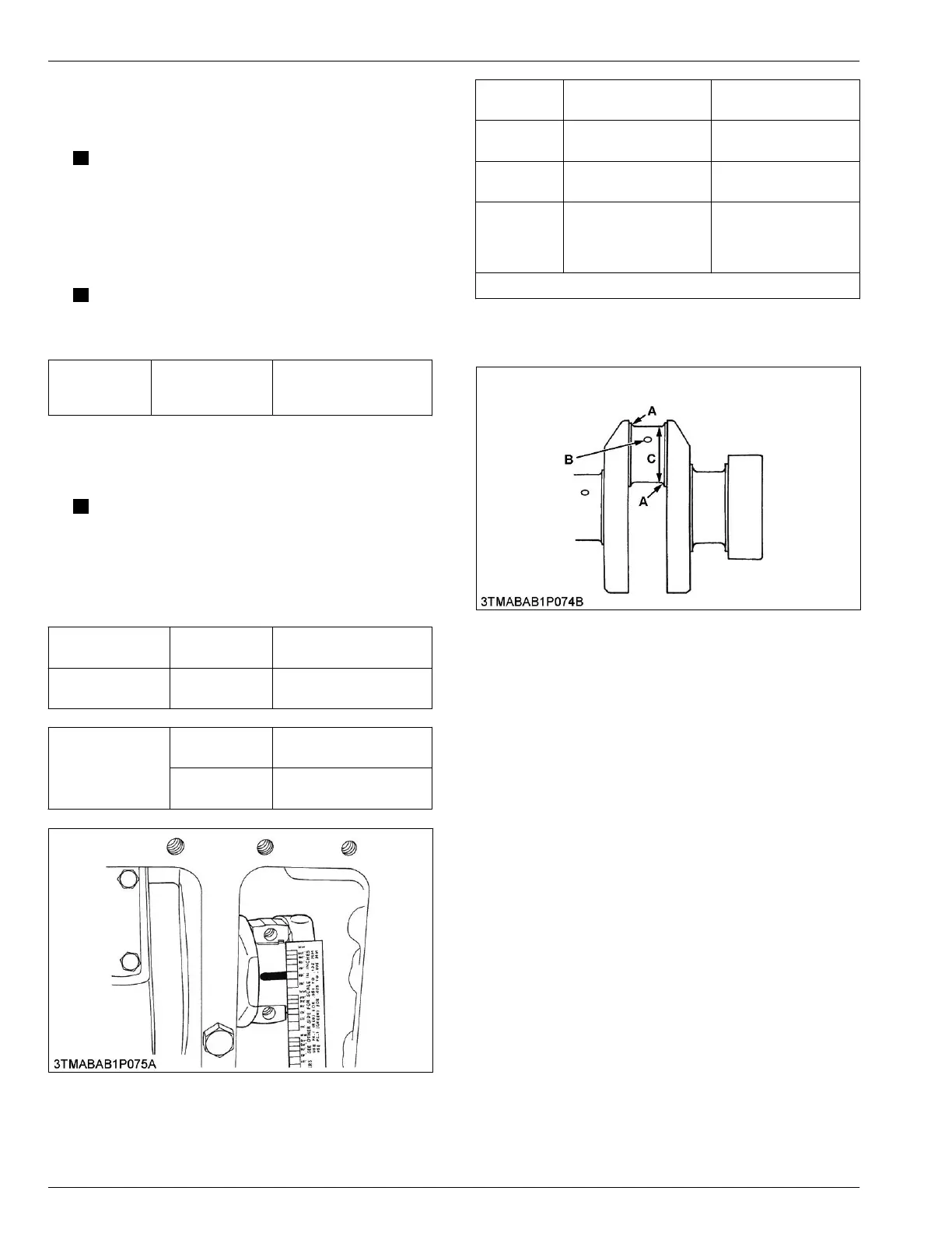
• Undersize dimensions of crankpin
Undersize
0.20 mm
0.0079 in.
0.40 mm
0.016 in.
Dimension A
2.8 to 3.2 mm radius
0.11 to 0.12 in. radius
2.8 to 3.2 mm radius
0.11 to 0.12 in. radius
Dimension
B
*
1.0 to 1.5 mm relief
0.040 to 0.059 in. relief
1.0 to 1.5 mm relief
0.040 to 0.059 in. relief
Dimension
C
39.759 to 39.775 mm
dia.
1.5654 to 1.5659 in.
dia.
39.559 to 39.575 mm
dia.
1.5575 to 1.5580 in.
dia.
The crankpin must be fine-finished to higher than Rmax = 0.8 S
* Holes to be de-burred and edges rounded with 1.0 to 1.5 mm
(0.040 to 0.059 in.) relief.
A: Dimension A
B: Dimension B
C: Dimension C
6.33 Checking oil clearance between
crankshaft journal and crankshaft
bearing 1
T
ools required
• Inside micrometer
• Outside micrometer
4. ENGINE
SER
VICING
6. Servicing
05-E4B SERIES,05-E4BG SERIES
 Loading...