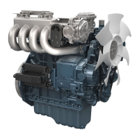
2. Move
the crankshaft to the front and rear to
measure the side clearance.
NOTE
• If the measurement
is more than the service
limit, replace the thrust bearings.
• If the same dimension bearing is not
applicable because of the crankshaft journal
wear, replace it with an oversize one. Refer
to the table and figure.
Side clearance of
crankshaft
Service specifi-
cation
0.15 to 0.31 mm
0.0059 to 0.012 in.
Service limit
0.50 mm
0.020 in.
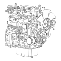
(Reference)
•
Oversize dimensions of crankshaft journal
Oversize
0.20 mm
0.0079 in.
0.4 mm
0.016 in.
Dimension
A
51.50 to 51.70 mm
2.028 to 2.035 in.
51.60 to 51.80 mm
2.032 to 2.039 in.
Dimension
B
28.20 to 28.25 mm
1.11
1 to 1.1
12 in.
28.40 to 28.45 mm
1.119 to 1.120 in.
Dimension
C
2.3 to 2.7 mm radius
0.091 to 0.10 in. radius
2.3 to 2.7 mm radius
0.091 to 0.10 in. radius
The crankshaft journal must be fine-finished to higher than Rmax
= 0.8 S.
A: Dimension A
B: Dimension B
C: Dimension C
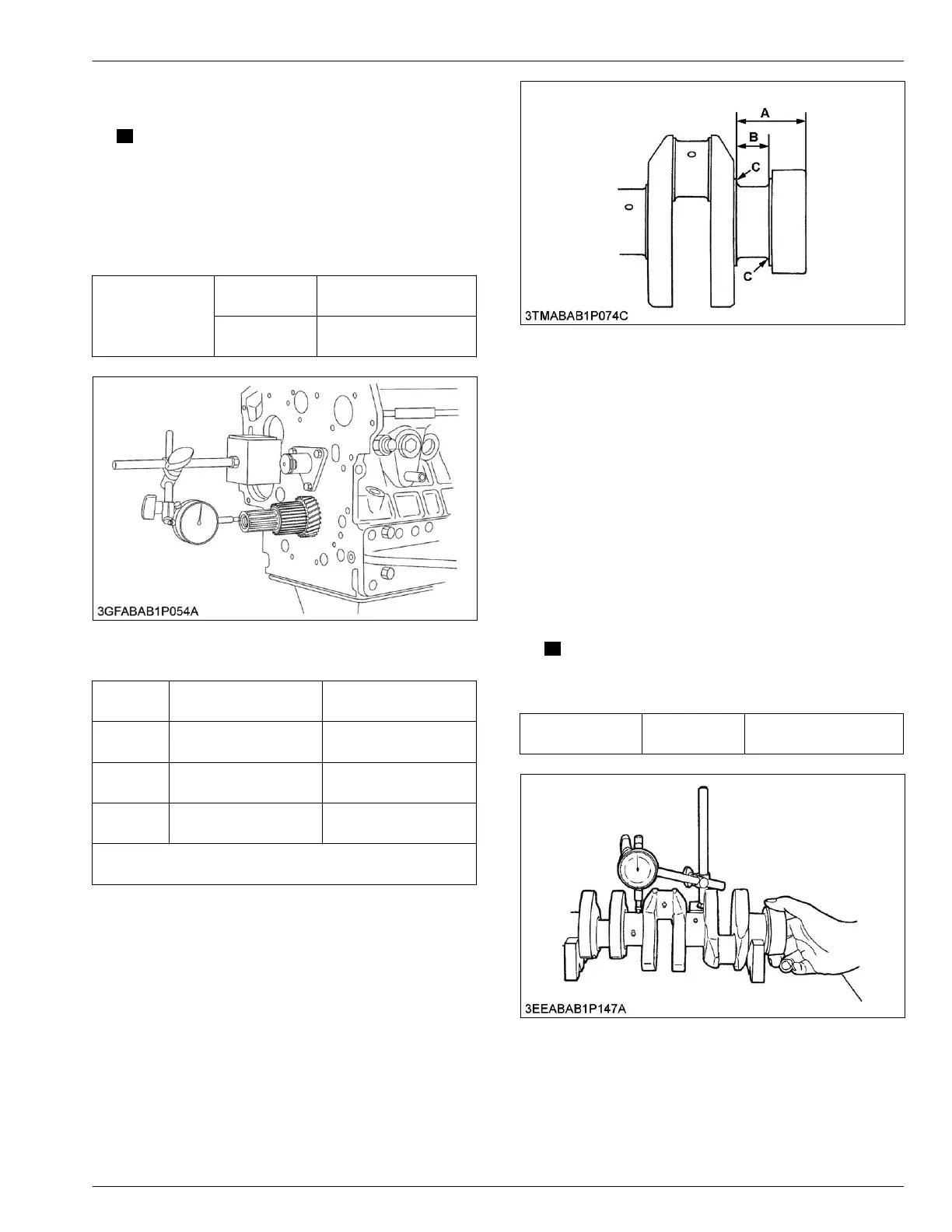
6.31 Checking crankshaft alignment
T
ools required
• V blocks
• Surface plate
•
Dial gauge
1. Hold the two end journals of crankshaft with V
blocks on the surface plate.
2. Set a dial gauge with its point on the middle journal.
3. Turn the crankshaft slowly and read the variation on
the indicator. Half of the measured value is the
alignment value.
NOTE
• If the measurement
is more than the service
limit, replace the crankshaft.
Crankshaft align-
ment
Service limit
0.02 mm
0.0008 in.
6.32 Checking oil clearance between
crankpin and crankpin bearing
Tools required
• Plastigauge
SERVICING
6. Servicing 4. ENGINE
05-E4B SERIES,05-E4BG SERIES
 Loading...