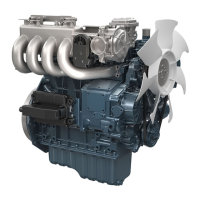
(1) Plastigauge
3. T
ake the piston to an intermediate position, install
the cylinder
head and tighten the cylinder head
mounting screw to the specified torque.
NOTE
• The polished cylinder
head mounting screw
with no marking on the screw head has
possibly used.
• In this case, tighten this screw to the same
torque as normal one.
Tightening tor-
que
Cylinder head
mounting screw
64 to 68 N⋅m
6.5 to 7.0 kgf⋅m
47 to 50 lbf⋅ft
4. Turn the crankshaft so the piston goes through
T.D.C.
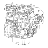
5.
Remove the cylinder head and compare the width
of the crushed plastigauges (2) with the scale (3).
NOTE
• Top clearance
= Width of the crushed
plastigauge (2)
• If they are out of service specification, check
the oil clearance of the crankpin, journal and
piston pins.
Top clear-
ance
Service
specifica-
tion
D1005-E4B/
E4BG
D1105-E4B/
E4BG
V1505-E4B/
E4BG
0.55 to 0.75 mm
0.022 to 0.029 in.
D1305-E4B/
E4BG
0.80 to 1.0 mm
0.032 to 0.039 in.
(2) Crushed plastigauge (3) Scale
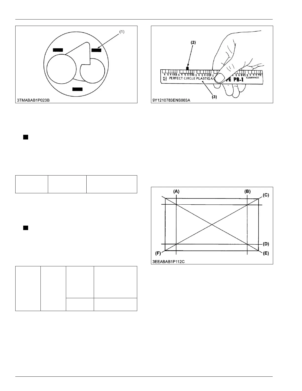
6.2 Checking cylinder head surface
flatness
Tools required
• Straightedge
• Feeler gauge
1.
Clean the cylinder head surface.
2. Place a straightedge on the cylinder head's four
sides (A), (B), (C) and (D) and two diagonal (E) and
(F) as shown in the figure.
4. ENGINE
SERVICING
6. Servicing
05-E4B SERIES,05-E4BG SERIES
 Loading...