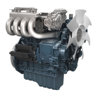
(1) Max. torque limiter
(6) Fork lever 1
(7) Floating lever
(8) Torque pin
(9) Fork lever 2
(10) Fuel limitation bolt
(a) Distance to which torque pin
(8) pushes fork lever 1 (6)
out
(b) Increase of fuel
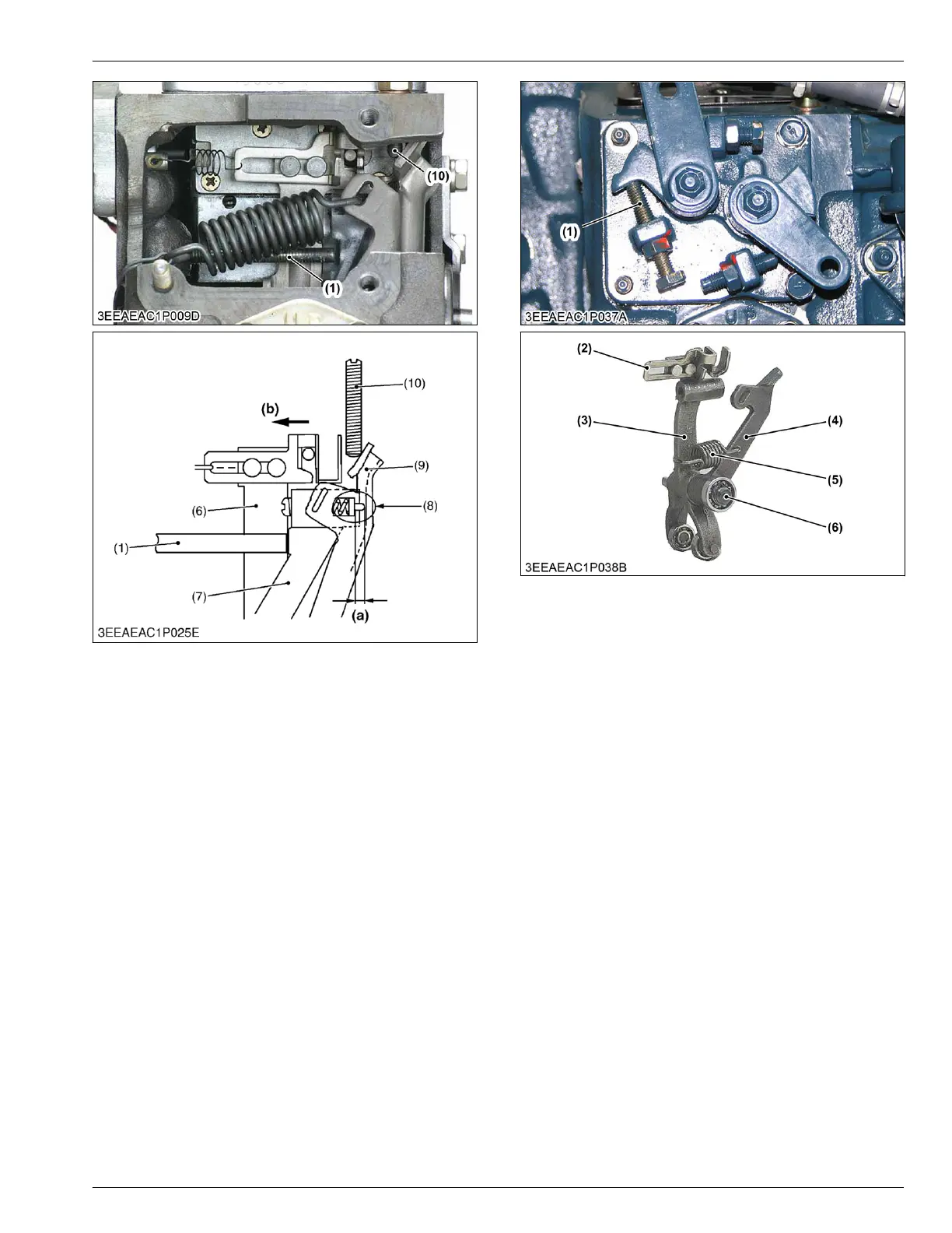
1.3.2 Structure of two lever type fork lever
(for BG type)
The engine speed of BG engine 1800 min
-1
(rpm)
specification.
The fork lever
assembly of BG series is consist of fork
lever 1 (3), fork lever 2 (4).
A slide plate is installed in fork lever 1. The governor
spring (5) is hooked to fork lever 2 (4).
The start spring is hooked to a slide plate, and holds
the control rack in the direction of full fuel position.
Fork lever 2 (4) and fork lever 1 (3) are installed with
the fork lever shaft (4).
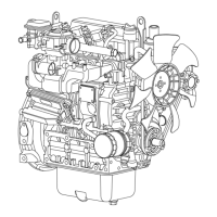
(1) Idle speed adjust bolt
(2) Slide plate
(3) Fork lever 1
(4) Fork lever 2
(5) Governor spring
(6) Fork lever shaft
MECHANISM
1. Engine body 4. ENGINE
05-E4B SERIES,05-E4BG SERIES
 Loading...