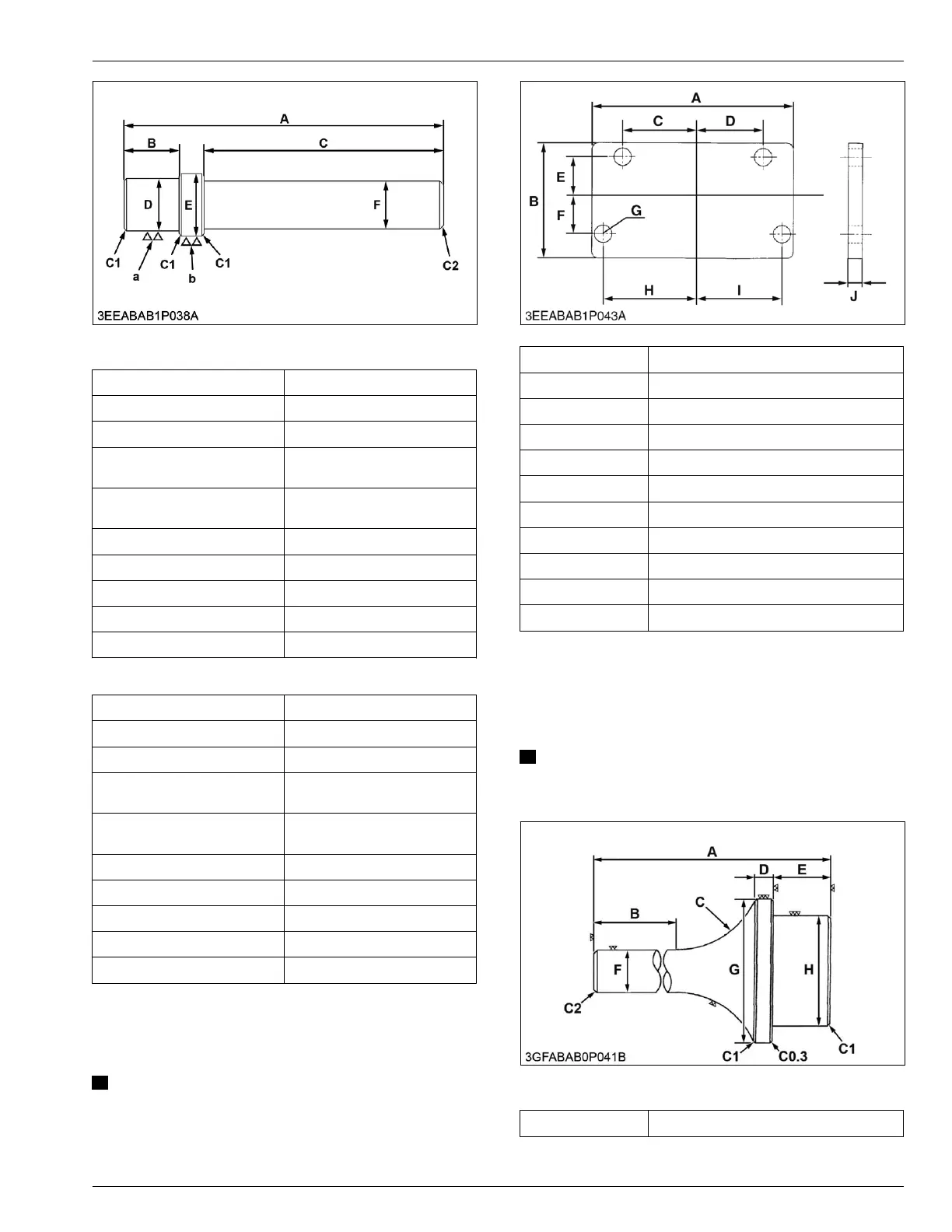
[For small end bushing]
A 157 mm (6.18 in.)
B 24 mm (0.94 in.)
C 120 mm (4.72 in.)
D
21.8 to 21.9 mm dia. (0.859 to
0.862 in. dia.)
E
24.8 to 24.9 mm dia. (0.977 to
0.980 in. dia.)
F 20 mm dia. (0.79 in. dia.)
a 6.3 μm (250 μin.)
b 6.3 μm (250 μin.)
C1 Chamfer 1.0 mm (0.039 in.)
C2 Chamfer 2.0 mm (0.079 in.)
[For idle gear bushing]
A 196 mm (7.72 in.)
B 26 mm (1.0 in.)
C 150 mm (5.91 in.)
D
25.80 to 25.90 mm dia. (1.016
to 1.019 in. dia.)
E
28.80 to 28.90 mm dia. (1.134
to 1.137 in. dia.)
F 20 mm dia. (0.79 in. dia.)
a 6.3 μm (250 μin.)
b 6.3 μm (250 μin.)
C1 Chamfer 1.0 mm (0.039 in.)
C2 Chamfer 2.0 mm (0.079 in.)
5. Flywheel stopper
Use for fixing the flywheel.
NOTE
• This special tool
is not provided, therefore
make it by referring to the figure below.
A 140 mm (5.51 in.)
B 80 mm (3.1 in.)
C 49.3 mm (1.94 in.)
D 49.3 mm (1.94 in.)
E 23.8 mm (0.937 in.)
F 23.8 mm (0.937 in.)
G 11 mm dia. (0.43 in. dia.)
H 56.5 mm (2.22 in.)
I 56.5 mm (2.22 in.)
J 8 mm (0.3 in.)
Material SS400
6. Crankshaft bearing 1
replacing tool
Use to press out and press fit the crankshaft bearing 1.
NOTE
• The special tools
are not provided, so make
them referring to the figure.
[Press out]
A 135 mm (5.31 in.)
(Continued)
SPECIAL TOOLS
5. Flywheel stopper 2. GENERAL
05-E4B SERIES,05-E4BG SERIES
 Loading...