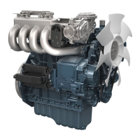
2. Measure
the
valve
stem O.D. with an outside
micrometer.
Valve stem O.D.
Service specifica-
tion
6.960 to 6.975 mm
0.2741 to 0.2746 in.
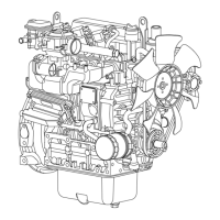
3. Measure
the
valve
guide I.D. with an inside
micrometer.
Valve guide I.D.
Service specifica-
tion
7.010 to 7.025 mm
0.2760 to 0.2765 in.
4. Calculate the clearance.
NOTE
• If the clearance
is more than the service
limit, replace the valves.
• If the clearance stays more than the service
limit, replace the valve guide also.
Clearance be-
tween valve stem
and valve guide
Service specifica-
tion
0.035 to 0.065 mm
0.0014 to 0.0025 in.
Service limit
0.10 mm
0.0039 in.
RELATED PAGE
6.7 Replacing valve guide on page 4-53
6.7 Replacing valve guide
IMPORTANT
• Do not hit
the valve guide with a hammer during
replacement.
Tools required
• Press tool
• Valve guide replacing tool
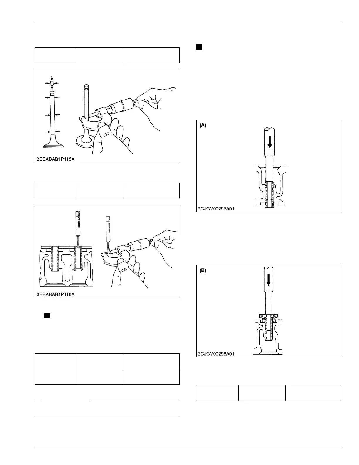
Removing valve guide
1. Press out the
used valve guide with the valve guide
replacing tool.
(A) Removing direction
Installing valve guide
1. Clean the new
valve guide and valve guide bore,
and apply engine oil to them.
2. Press fit the new valve guide with the valve guide
replacing tool.
(B) Installing direction
3. Ream
accurately the I.D. of the valve guide to the
specified dimension.
Valve guide I.D.
Service specifica-
tion
7.010 to 6.025 mm
0.2760 to 0.2765 in.
SERVICING
6. Servicing 4. ENGINE
05-E4B SERIES,05-E4BG SERIES
 Loading...