3. T
urn the flywheel counterclockwise (viewed from
flywheel
side)
until the fuel fills up to the hole of the
delivery valve holder (3) for No. 1 cylinder.
4. After the fuel fills up to the hole of the delivery valve
holder for No. 1 cylinder, turn back (clockwise) the
flywheel around 1.6 rad (90°).
5. Turn the flywheel counterclockwise to set at around
0.44 rad (25°) before T.D.C..
6. Slowly turn the flywheel counterclockwise and stop
turning when the fuel begins to come up, to get the
present injection timing.
7. Check to if the timing angle lines on the flywheel is
aligned with the center of timing window (2).
The flywheel has mark [1TC], [10] and [20] for the
crank angle before the top dead center of No. 1
cylinder.
8. If injection timing is out of adjustment, readjust the
timing with shims.
Injection tim-
ing
(3000 min
-1
(rpm))
Service
Specifica-
tion
D1005-
E4B
0.3011 to
0.3272 rad
(17.25 to 18.75°)
before T.D.C.
Injection tim-
ing
(3200 min
-1
(rpm))
D1005-
E4B
0.3360 to
0.3621 rad
(19.25 to 20.75°)
before T.D.C.
Injection tim-
ing
(3000 min
-1
(rpm))
D1105-
E4B
0.301
1 to
0.3272 rad
(17.25 to 18.75°)
before T.D.C.
Injection tim-
ing
(2600 min
-1
(rpm))
D1305-
E4B
0.2622 to
0.2923 rad
(15.25 to 16.75°)
before T.D.C.
Injection tim-
ing
(2300 min
-1
(rpm))
V15005-
E4B
0.2313 to
0.2574 rad
(13.25 to 14.75°)
before T.D.C.
Injection tim-
ing
(1800 min
-1
(rpm))
D1005-
E4BG,
D1105-
E4BG,
0.2575 to
0.2836 rad
(14.75 to 16.25°)
before T.D.C.
Injection tim-
ing
(1800 min
-1
(rpm))
D1305-
E4BG,
V1505-
E4BG,
0.2487 to
0.2748 rad
(14.25 to 15.75°)
before T.D.C.
12.2 Checking injection pump
NOTE
• Never try to
disassemble the injection pump
assembly. For repairs, you are strongly
requested to contact a Kubota-authorized pump
service shop.
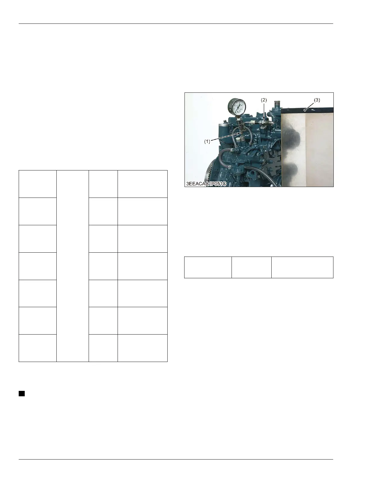
Tools required
• Injection pump pressure tester
Fuel tightness of pump element
1. Remove the engine stop solenoid.
2. Remove the injection pipes and glow plugs.
3.
Install the injection pump pressure tester to the
injection pump.
4. Install the injection nozzle (2) jetted with the proper
injection pressure to the injection pump pressure
tester (1).
(1) Injection pump pressure test-
er
(2) Injection nozzle
(3) Protection cover for jetted
fuel
5.
Set
the speed control lever to the maximum speed
position.
6.
Operate the starter to increase the pressure.
7.
If the pressure can not reach the service limit,
replace the pump with new one or repair with a
Kubota-authorized pump service shop.
Fuel tightness of
pump element
Service limit
13.73 MPa
140.0 kgf/cm
2
1991 psi
Fuel tightness of delivery valve
1. Remove the engine stop solenoid.
2. Remove the injection pipes and glow plugs.
3.
Set a pressure tester to the fuel injection pump.
4. Install the injection nozzle (2) jetted with the proper
injection pressure to the injection pump pressure
tester (1).
3. MAINTENANCE
CHECK AND MAINTENANCE
12. Check points of every 3000 hours
05-E4B SERIES,05-E4BG SERIES
 Loading...