• Apply
engine oil to the oil seal (5) lip and be careful
that it is not rolled when installing.
•
T
ighten the bearing case cover mounting screws
with even force on the diagonal line.
• Tighten to the specified tightening torque.
Tightening tor-
que
Bearing case cov-
er mounting screw
10.8 to 12.2 N⋅m
1.10 to 1.25 kgf⋅m
7.96 to 9.04 lbf⋅ft
RELATED PAGE
6.30 Checking side clearance of crankshaft on page
4-64
5.26 Removing crankshaft assembly
(except D1305-E4B/E4BG)
IMPORTANT
• Be careful to
protect crankshaft bearing 1 from
scratches, caused by the crank gear, etc.. (Wrap
the gear in vinyl tape, etc.)
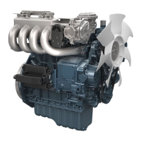
1. Remove the main bearing case screw 2 (1).
(2) Main bearing case screw 2
2. Pull out the crankshaft assembly.
(When reassembling)
• Clean
the oil
passage of the crankshaft with
compressed air.
• Apply oil to the main bearing case screw 2 (1).
• Install the crankshaft assembly, aligning the screw
hole of main bearing case with the screw hole of
crankcase.
• Tighten to the specified tightening torque.
Tightening tor-
que
Main bearing case
screw 2
49 to 53 N⋅m
5.0 to 5.5 kgf⋅m
37 to 39 lbf⋅ft
5.27 Removing crankshaft assembly
(D1305-E4B/E4BG)
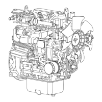
1. Remove the main bearing case screw 2.
2. T
urn the crankshaft to set the crankpin of the third
cylinder to the "A". Then draw out the crankshaft
until the crankpin of the second cylinder comes to
the center of the third cylinder.
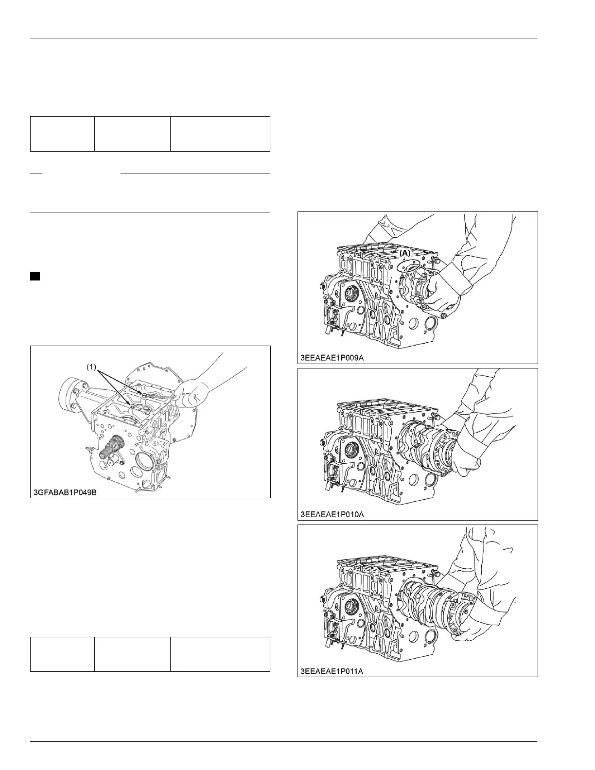
3. Turn the crankshaft by 2.09 rad (120°)
counterclockwise to set the crankpin of the second
cylinder to the "A". Draw out the crankshaft until the
crankpin of the first cylinder comes to the center of
third cylinder.
(A) Cut place for removing and
installing the crankshaft
4. Repeat
the these
steps to draw out all the
crankshaft.
4. ENGINE
SERVICING
5. Disassembling and assembling
05-E4B SERIES,05-E4BG SERIES
 Loading...