2KL/2KK
2-1-3
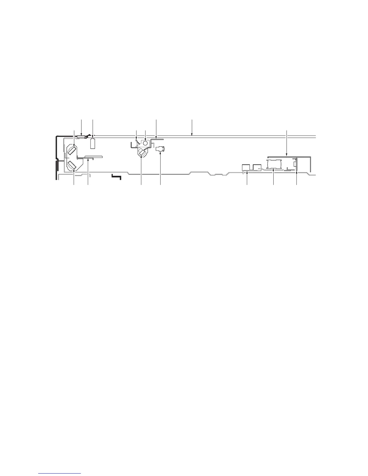
2-1-2 Optical section
The optical section consists of the image scanner section for scanning and the laser scanner section for printing.
(1) Image scanner section
The original image is illuminated by the exposure lamp (EL) and scanned by the CCD PWB (CCDPWB) in the image scan-
ning unit via the three mirrors, the reflected light being converted to an electrical signal.
The scanner and mirror frames travel to scan on the optical rails on the front and rear of the machine to scan from side to
side. The speed of the mirror frames is half the speed of the scanner.
When the DP is used, the scanner and mirror frames stop at the DP original scanning position to start scanning.
Figure 2-1-3 Image scanner section
7 5
6
2 103
12 13 111
4 14 815 9
(1) Mirror 1 frame
(2) Exposure lamp (EL)
(3) Mirror 1
(4) Scanner reflector
(5) Mirror 2 frame
(6) Mirror 2
(7) Mirror 3
(8) ISU
(9) CCD PWB (CCDPWB)
(10) ISU cover
(11) Contact glass
(12) Slit glass
(13) Home position switch (HPSW)
(14) Original detection switch (ODSW)
(15) Original size detection sensor (OSDS)
 Loading...