55
LeeBoy Model 8510E Conveyor Paver 5-23
Maintenance
Replacement Procedures
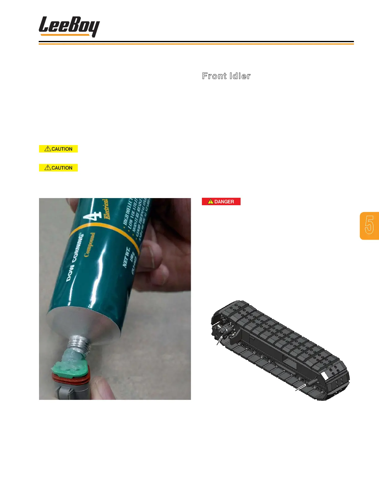
Front Idler
Follow this procedure for replacing the front idler
(Figure 5-29):
1. Raise conveyor and insert safety prop. (Page 5-6)
NOTE: Perform this additional step for poly or steel
tracks only: Locate track tensions manifold
and back the relief cartridge out of the
aluminum block about three turns until you
hear the tension pressure release.
2. Rotate the track so the master pin is at the rear
bottom of the front idler.
3. Jack up the paver at least two feet (61 cm) off
the ground for enough clearance under the
undercarriage to perform this procedure.
Crush hazard! Always use safety
blocks in addition to jack when working under the
paver to prevent serious injury or even death.
4. Remove the clip pin from the cylinder rod and idler
bracket. Idler will slide out.
5. Remove the idler bracket and bolt to the new idler.
6. Install idler, ensuring cylinder and clip pin are
aligned properly.
7. Lower sprocket back down toward the track
chain,ensuring the sprocket is about one (1) inch
(2.54 cm) from the chain.
Sprocket
Front
Idler
Figure 5-29. Front Idler
To correctly apply dielectric grease:
• Apply a thin, visible, uniform coat using ONLY high-
quality dielectric grease (Dow Corning 4 or equivalent)
across the MALE connector as shown in Figure 5-27.
• Coating too thin may not ll the gaps between
pins.
• Coating too thick may prevent proper
connection or force pins or seals out. (Figure
5-28)
• Plug in the male connector.
DO NOT force connector to lock if too
much grease has been applied.
Excessive grease application does
not allow a proper connection by preventing the
plugs from locking into place, and can cause damage
to the connector seals.
Figure 5-28. Incorrect Application of Dielectric
Grease