4
LeeBoy 8510E Conveyor Paver 4-3
Operation
Receiving the Machine
The LeeBoy Model 8510E Conveyor Paver is equipped
with hydrostatic-driven tracks that propel the paver
using friction-controlled joysticks. The amount
of steering is controlled by the amount of joystick
movement and the speed of the paver. Engine RPM is
set using the PV480 digital display unit on the operator
control panel. Always set throttle before starting to
pave.
Only authorized personnel who are
properly trained should operate the LeeBoy Model
8510E Conveyor Paver.
Although the machine has been checked thoroughly by
the manufacturer, road hazards or other factors during
transport may result in damage. Inspect machine for
any damage during transport. Contact your authorized
dealer immediately if any damage has occurred.
Initial and Daily Inspection
The following inspection is essential and should be
performed before the initial start-up. Visually inspect the
unit to check its general condition and for familiarization.
Continue with a check of the systems and components
shown in Table 4-1 below:
Table 4-1. Initial Inspection
INSPECT PROCEDURE
Engine Oil
Level
Maintain oil level between ADD and
FULL marks on dipstick.
Fuel Tank
Check for adequate fuel supply. Fill if
needed. Always ll tank at end of the day
to prevent condensation in the tank.
Hydraulic
Tank
Check the tank for oil level and leaks.
Radiator Check coolant level.
Battery
Ensure all cables are tight and clean.
Check for corrosion on the battery
terminals.
Air Cleaner
Check the air lter element and hose
connections. Air cleaner has both a
primary and secondary lter.
Drain Plugs Make sure plugs are inserted and tight.
Engine Belt Check for proper belt tension.
Grease
Fittings
Ensure ttings are greased and in good
working order.
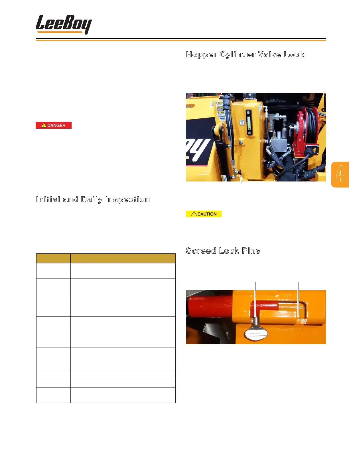
Hopper Cylinder Valve Lock
The hopper cylinder valve can be used to lock the
hopper wings when they are open or closed. (Figure
4-1) Turn the valve counterclockwise to unlock the
hopper wings and clockwise to lock the hopper wings.
Hopper Cylinder Lock Valve
Figure 4-1. Hopper Cylinder Lock Valve
Ensure screed lock pins and hopper
cylinder valves are unlocked before extending or
retracting the screed or hopper wings.
Screed Lock Pins
Screed lock pins (one on each side) adds additional
safety and stability during operation and transport.
Locked
Unlocked
Figure 4-2. Screed Lock Pin
Figure 4-2 shows lock pin in the locked position.
To lock and unlock the screed lock pins:
• Loosen thumb screw, lift up and slide to the desired
locked or unlocked position.
• Lower into desired position and retighten thumb
screw.