4
LeeBoy 8510E Conveyor Paver 4-27
Operation
6. Turn the tilt screw so the front of the endgate tilts
down slightly when the screed is lifted. This will allow
the endgate to set itself to the grade. (Figure 4-46)
NOTE: Never allow the endgate to carry the weight of
the screed to prevent uneven compaction.
Figure 4-46. Endgate Tilt Screw Adjustment
7. If the endgate digs into the asphalt at the front,
adjust the tilt screw until the endgate tilts back more.
8. When making a hot joint, the endgate must be set to
where it ts ush with bottom of screed.
9. On the rst pass, leave approximately six to eight
inches (15 - 20 cm) of unrolled asphalt where the
joint will be made.
10. When making a joint, the endgate must be set to
where it ts ush with bottom of screed.
NOTE: Keep runners clean. When making a joint,
spray solvent on the runners.
11. If the joint looks too high or too low, adjust the ight
screw on the screed one turn at a time and allow
four to ve feet (1.2 - 1.4 m) of travel to correct itself.
NOTE: Too much adjustment up or down may cause
uneven pavement.
12. If making a cold joint, set the endgate down about
1/4 inch (6.35 mm) for a nice, even edge.
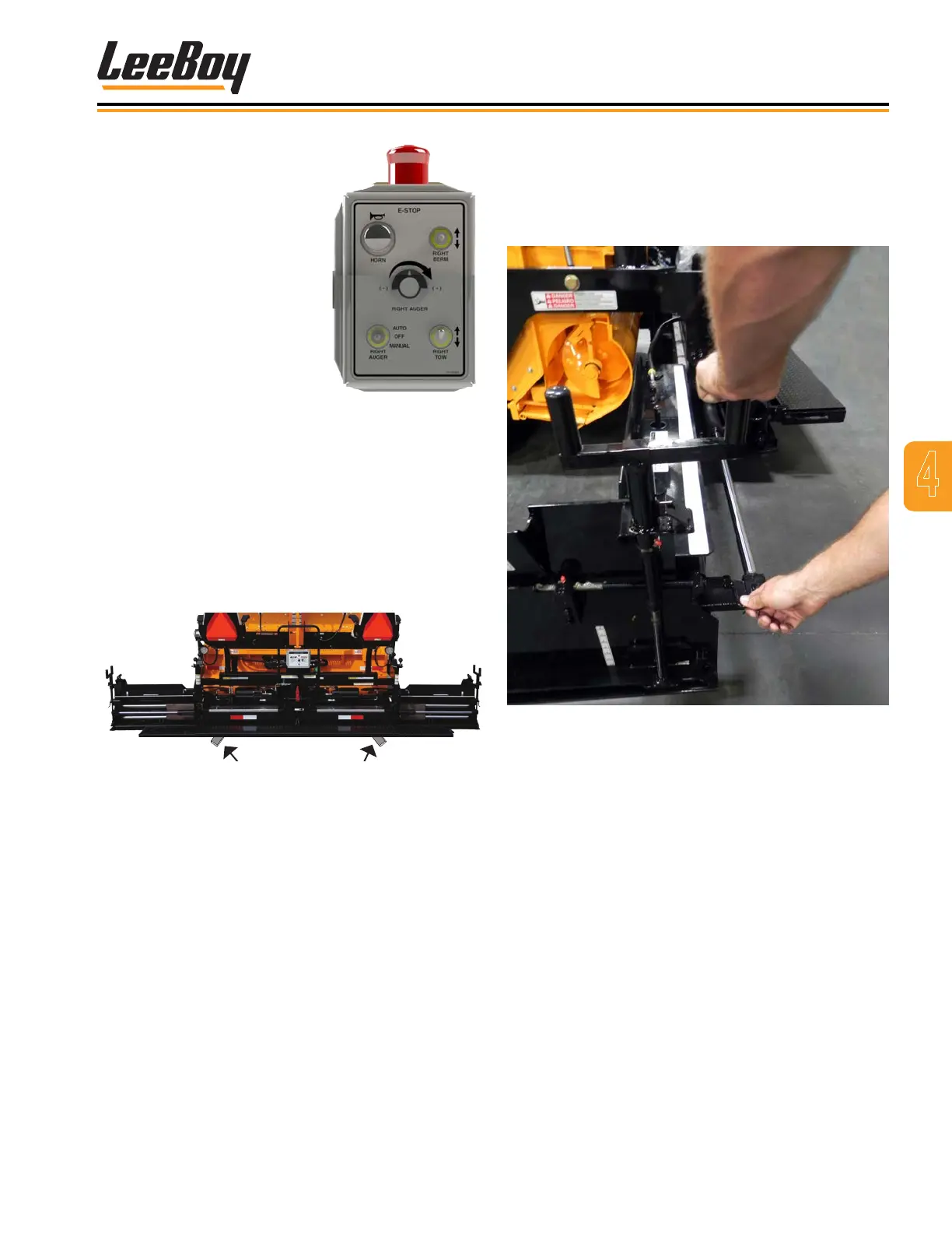
Figure 4-44. Remote
Screed Control Box
A remote control box is
provided on both sides
of the main screed with
switches to extend or retract
the screed, sound horn,
E-Stop button for immediate
stopping, turn the auger on
and off with auger dial for
speed, berm switch and
tow switch. (Figure 4-44)
Adjust the screed extension while paving using the
following procedures:
1. Move paver to the starting position for paving.
2. Extend the screed to the desired width.
3. To set the depth, you can place a small starter block
under the screed while you make adjustments.
(Figure 4-45)
Figure 4-45. Starter Blocks Location
4. Level the screed using the electric ight screw
(Figure 4-42):
• Refer to the elevation gauge (one on each side
of the paver for your convenience). Raise or
lower until the rod end of the cable is ush with
“0” on the gauge.
NOTE: Both joysticks must be in the forward position
to operate the electric ight screw on the left
side, but will work at any time in the MANUAL
position.
• While paving, refer to both gauges and make
minor adjustments if needed.
5. On the rst pass, turn the endgate depth screw to
lower the endgate until it is about 1/4-inch (6.35 mm)
below the screed. (Figure 4-43)