6. Function Description
6-20
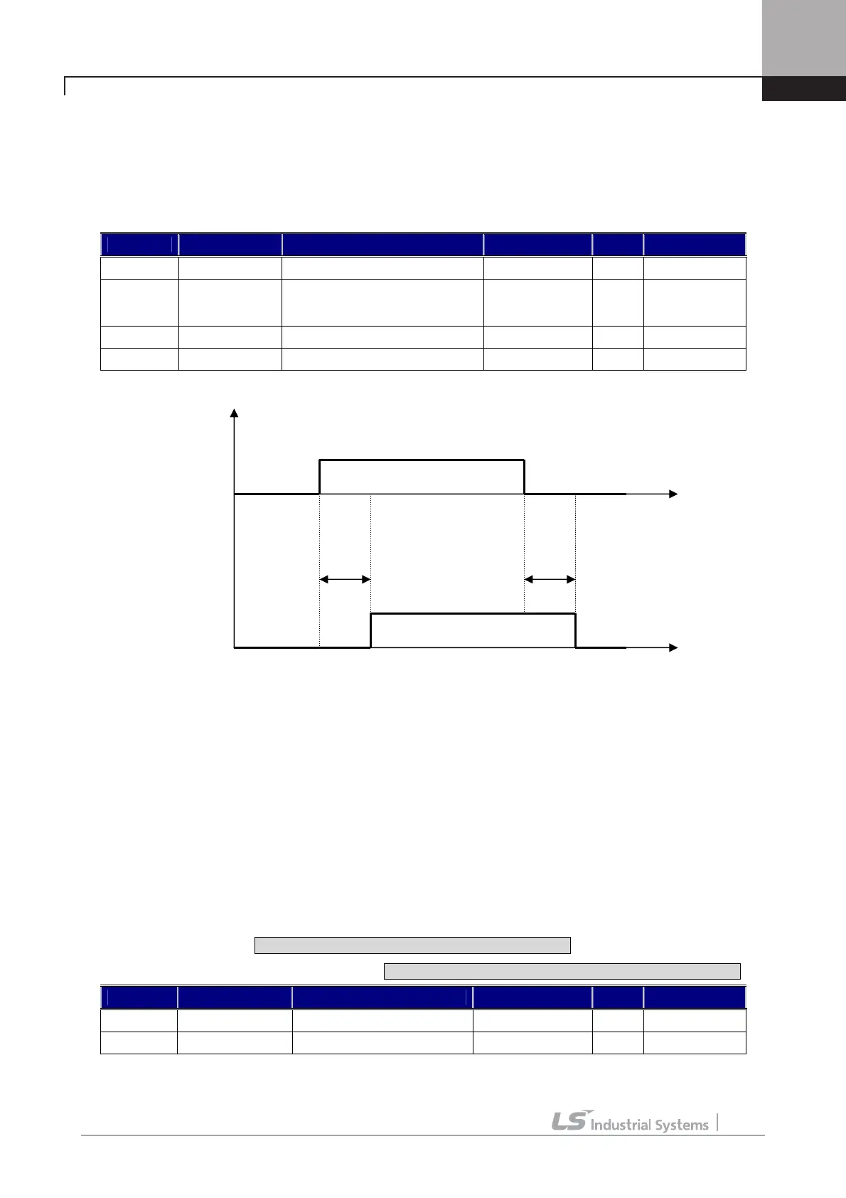
2.8) Timer out
Timer Out acts as an output signal to the timer input signal defined in the one of the multi-function input terminals
P1~P7 and it uses the set values of Timer On delay time at I/O_55 and of Timer Off delay time at I/O_56. The example
of code setting is shown in the table below when I/O_07 is set to Timer Input and I/O_41 is set to Timer Output.
Code Display Description Range Unit Default
DIO_07 P7 define Definition of P7 Timer Input
DIO_41 AX1 Define
Definition of multi-function
output terminal relay output 1
(1A, 1B)
Timer Out
DIO_55 TimerOn Dly Timer ON delay 0.1 ~ 3600.0 sec 0.1
DIO_56 TimerOff Dly Timer OFF delay 0.1 ~ 3600.0 sec 0.1
2.9) LV
LV is enabled when the DC link voltage of the inverter is less than the detecting level of low voltage alarm.
2.10) Run
It is ON when the inverter is running.
2.11) Regenerating
It is ON when the motor is regenerating.
2.12) Mot OH Warn (Motor Overheat Warning)
Using NTC or PTC signal built in the motor, Motor Overheat is ON when the temperature inside the motor is higher
than the overheat alarm level. This signal is only for an alarm, not for the inverter trip.
※In the case of ExTTN_I/O it corresponds to Ai5 Ai3 Define[AIO_25 ] is set to “Use Mot NTC” or “Use Mot PTC”.
Code Display Description Range Unit Default
DIO_64 MH Warn Temp Motor overheat detect 75 ~ 130
°C
120
DIO_65 MH Warn Band MH hysterisis band 0 ~ 10
°C
5
DIO_55 DIO_56
P7
1A
Timer ON Delay Timer OFF Delay
OFF OFF ON
ON OFF OFF

 Loading...


