262335 63 Revision A
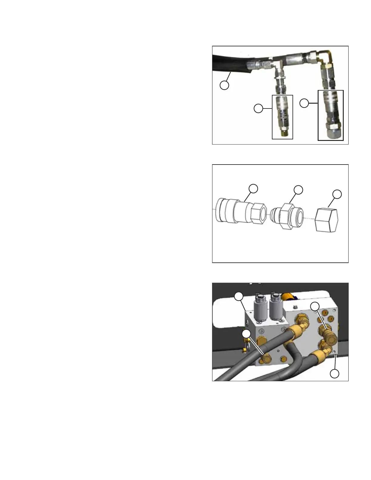
Figure 3.117: Header Hose Bundle
3. Remove female coupler assemblies (A) and (B) from hoses
in bundle (C) from header.
Figure 3.118: Large Coupler Assembly
4. Remove and discard cap (A) and adapter fitting (B)
(including O-ring) from large coupler (C).
Figure 3.119: Manifolds without Reverser Manifold
Configured for Auger Header – M155 Shown, M200
Similar
5. Install larger coupler (D) onto fitting at port R2 on
manifold (B).
6. Remove cap from smaller coupler assembly (C) and install
assembly in port R2 on manifold (A).
IMPORTANT:
Make sure O-ring is on JIC threads in port R1 to ensure a
proper seal with coupler (D). If O-ring is missing, reuse O-
ring from discarded adapter fitting in Step 4, page 63.
7. Return to Step 18, page 51.
ASSEMBLING THE MACHINE