214327 278 Revision B
Figure 8.14: Hydraulic Fitting
1. Ensure that the sealing surfaces and the fitting threads are
free of burrs, nicks, scratches, and any foreign material.
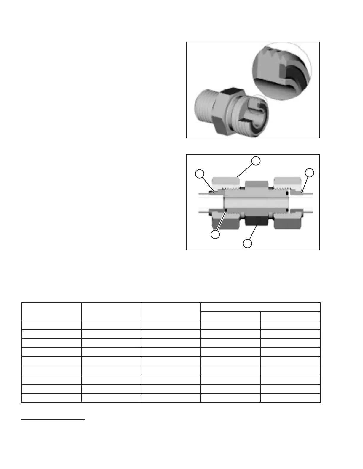
Figure 8.15: Hydraulic Fitting
2. Apply hydraulic system oil to O-ring (B).
3. Align the tube or hose assembly so that the flat face of
sleeve (A) or (C) comes into full contact with O-ring (B).
4. Thread tube or hose nut (D) until it is hand-tight. The nut
should turn freely until it bottoms out.
5. Torque the fittings according to values in Table 8.14, page
278.
NOTE:
If applicable, hold the hex flange on fitting body (E) to
prevent the rotation of the fitting body and the hose when
tightening fitting nut (D).
6. Use three wrenches when assembling unions or joining two
hoses together.
7. Verify the final condition of the fitting.
Table 8.14 O-Ring Face Seal (ORFS) Hydraulic Fittings
SAE Dash Size
Thread Size (in.) Tube O.D. (in.)
Torque Value
60
Nm
lbf·ft
-3
Note
61
3/16
––
-4
9/16 1/4
25–28 18–21
-5 Note
61
5/16
––
-6
11/16 3/8
40–44 29–32
-8
13/16 1/2
55–61
41–45
-10 1
5/8
80–88 59–65
-12
1 3/16 3/4
115–127 85–94
-14
Note
61
7/8
––
-16
1 7/16
1 150–165
111–122
REFERENCE
60. Torque values and angles shown are based on lubricated connection as in reassembly.
61. O-ring face seal type end not defined for this tube size.