13
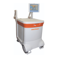
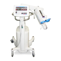
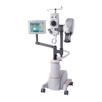
2 - System Basics
1. Display – Color touch screen display used to control the Intego™ PET Infusion System,
view delivery data, and report radioactivity within the system.
2. USB Port – Provides the operator the capability of importing and exporting data.
3. Shielded Chamber – Lead shielded compartment that houses the SAS, RP, and various
other system components.
4. Shielded Chamber Lid – A sliding lid that allows access to the components and RP
contained in the Shielded Chamber.
5. Shielded Chamber Lid Latch – Used to secure the Shielded Chamber Lid from
unintentional opening.
6. PAS Compartment – not shown – A separate compartment of the Shielded Chamber.
Provides shielding for the PAS (located under the PAS Compartment Cover).
7. PAS Compartment Cover – Hinged cover to access the PAS Compartment.
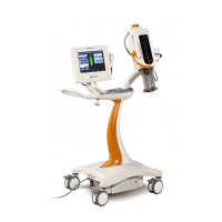
8. On/Shutdown/Standby Button – Turns the Intego™ PET Infusion System On and Off.
Also used to place the Intego™ PET Infusion System into and out of Standby. Also used
to lock and unlock the system.
9. Stop Button – Used to stop current operation of the Intego™ PET Infusion System.
10. Power Switch – Rocker switch used to turn AC power On or Off.
11. Saline Pump – Peristaltic pump used to circulate saline in the SAS.
12. Saline Hook – Used for hanging the Saline Container.
13. Printer – Used to print patient-specific infusion records.
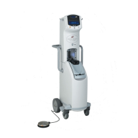
14. Cable Storage – Posts used for wrapping the power cable when the Intego™ PET
Infusion System is being moved or when not in use.
15. Caster Brakes – Used to secure the Intego™ PET Infusion System from movement when
parked.
The following apply only to INT SYS 200 systems.
16. Drive Controller – Thumb wheel to control forward/reverse variable speed.
17. Drive Engage Switch – Used to enable the Drive System.
18. Drive Speed Switch – Used to select the speed range of forward movement.
19. Drive Override – Mechanism to override the Drive System.
20. Status Indicators – Provides battery, Dose Calibrator, and Drive System status.
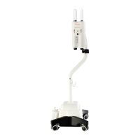
The following apply only to INT SYS 100 systems.
21. Brake Release – Located on each handle, used to release the primary brakes.
22. Status Indicators – Provides battery and Dose Calibrator status.