5-29
6. If the BIS and NMT modules are configured, perform the following patient auxiliary current
tests between each electrode and the others by turns:
Normal polarity;
Reverse polarity;
Normal polarity with open neutral;
Reverse polarity with open neutral;
Normal polarity with open earth;
Reverse polarity with open earth;
7. Verify that the maximum leakage current does not exceed 100 μA (0.1 mA) in the first two
tests. While for the last two tests, verify that the maximum leakage current does not exceed
500 μA (0.5 mA).
Ensure the safety analyzer is authorized by certificate organizations (UL, CSA,
AAMI, etc.). Follow the instructions of the analyzer manufacturer. Fluke ESA620
is used as an example.
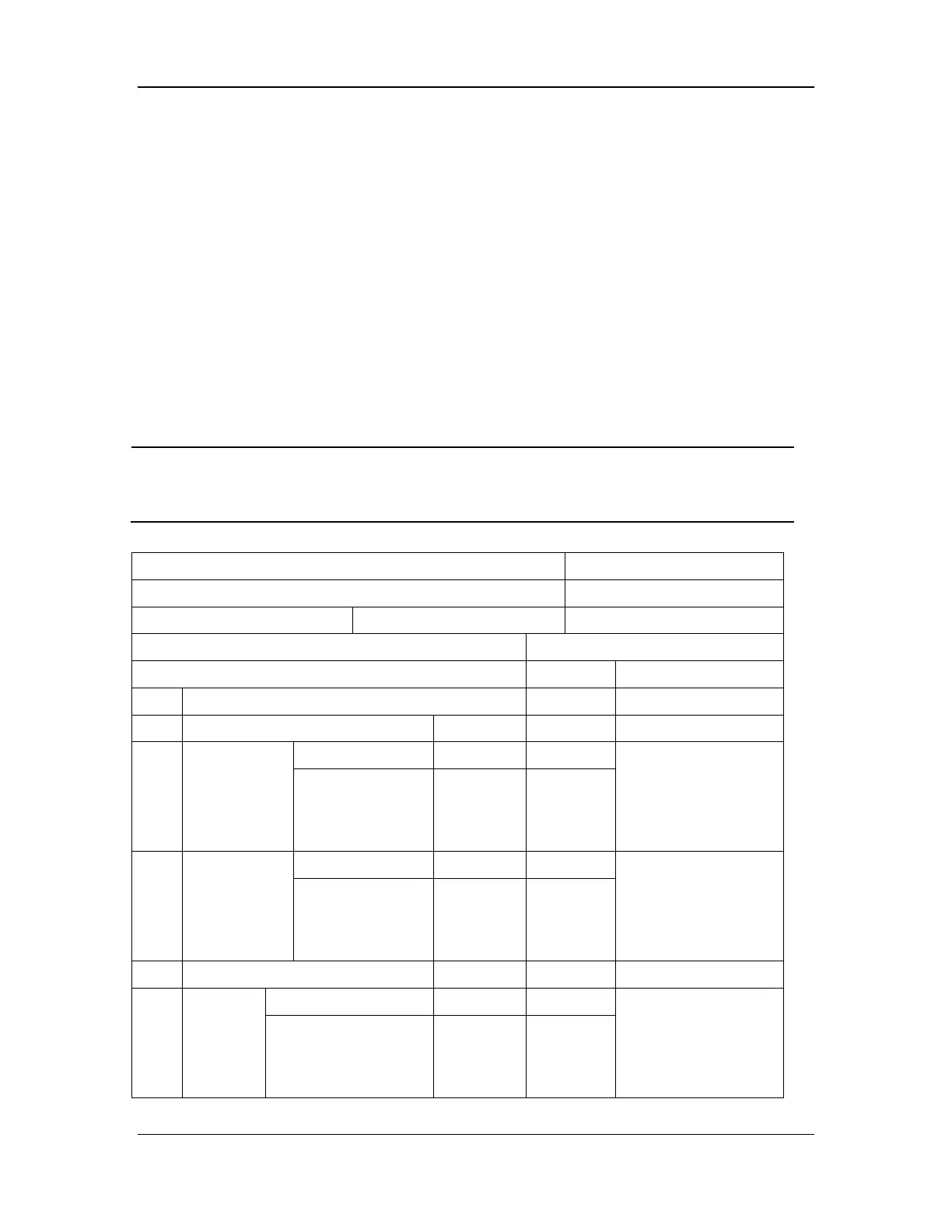
Electrical safety inspection form
Location: Technician:
Equipment: Control Number:
Manufacturer: Model: SN:
Measurement Equipment/SN: Date of Calibration:
Inspection and Testing Pass/Fail Limit
1 Auxiliary mains output voltage
2 Earth resistance Ω Max 0.1 Ω
3
Earth leakage
current
Normal condition ____μA Max:
Normal condition: 500
μA
Single fault condition:
1000 μA
Single fault
condition
____μA
4
Patient
leakage
current
Normal condition ____μA Max:
Normal condition: 100
μA
Single fault condition:
500 μA
Single fault
condition
____μA
5 Mains on applied part ____μA Max: 5000 μA
6
Patient
auxiliary
current
Normal condition ____μA Max:
Normal condition: 100
μA
Single fault condition:
500 μA
Single fault condition ____μA