2-69
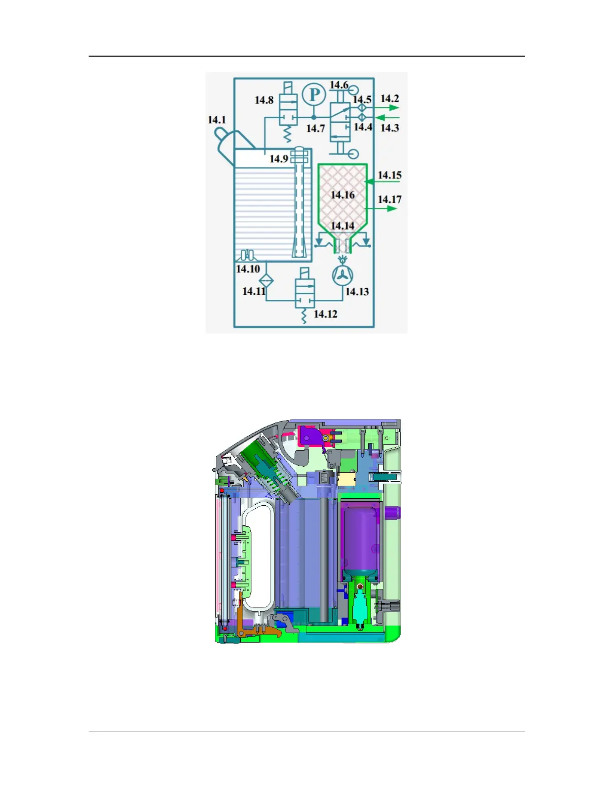
Figure 20 Pneumatic diagram of the electronic vaporizer
The electronic vaporizer consists of the drive gas interfaces (14.2 and 14.3), mechanical pressure
relief assembly (14.6), filling unit (14.1), main pneumatic block assembly, drug pool entrance
safety valve (14.8), drug pool, liquid level monitoring units (ultrasonic low liquid level
monitoring (14.10), capacitive continuous liquid level monitoring (14.9), and glass tube liquid
level display), locking unit, drug pool exit safety valve (14.12), base assembly, and mixing
chamber assembly (14.16). The structural diagram of the electronic vaporizer is shown below.
Figure 21 Structural diagram of the electronic vaporizer