2-70
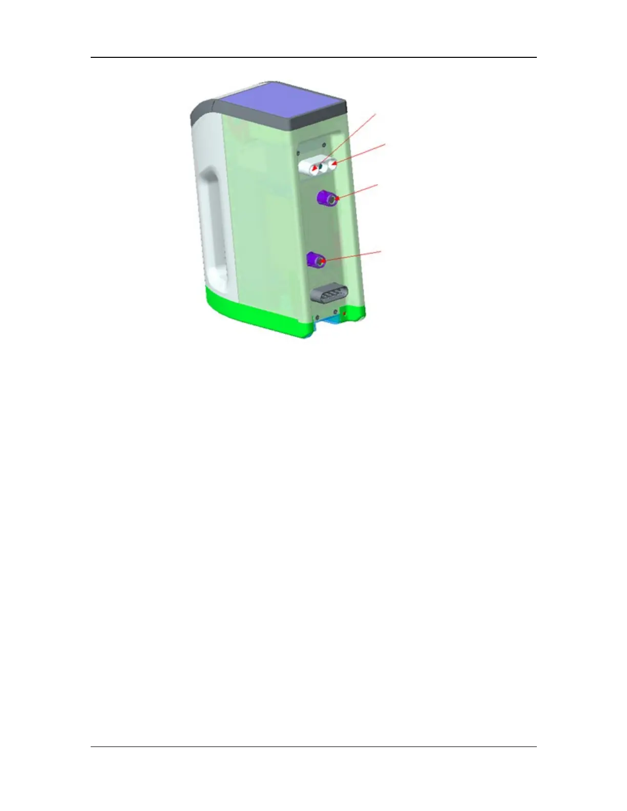
Figure 22 Interfaces of the electronic vaporizer
2.3.4.3 Electronic Vaporizer Manifold Assembly (for A9)
The electronic vaporizer manifold assembly provides a mounting location for the electronic
vaporizer, provides driving pressure for the drug pool of the electronic vaporizer, mixes the
O2/air mixture at the input end with the anesthetic gas in the electronic vaporizer to form fresh
gas, and delivers the fresh gas to the common gas outlet.
The schematic diagram of the electronic vaporizer manifold assembly is shown below. The drive
gas from the front gas inlet is divided into six ways. Three ways provide driving pressure for the
large-diameter valve (13.3) in the bypass branch, the large-diameter valves (13.12 and 13.13) in
the branch of canister 1, and the large-diameter valves (13.5 and 13.6) in the branch of canister 2.
Two ways provide driving pressure for the pneumatically-controlled lock (13.15) of canister 1
and the pneumatically-controlled lock (13.17) of canister 2. The remaining one way provides
driving pressure for the electronic vaporizer after the pressure is regulated to 150±5 kPa (22 psi)
through the regulator (13.1). The three-way valve (13.2) is used to switch on/off the bypass
branch. The three-way valve (13.11) is used to switch on/off the branch of canister 1. The
three-way valve (13.4) is used to switch on/off the branch of canister 2. The three-way valve
(13.8) is used to control the pressurization/relief of the drive gas in canister 1. The three-way
valve (13.7) is used to control the pressurization/relief of the drive gas in canister 2. The
three-way valve (13.14) is used to control the pressurization/relief of the
pneumatically-controlled lock drive gas in canister 1. The three-way valve (13.16) is used to
control the pressurization/relief of the pneumatically-controlled lock drive gas in canister 2. The
large-diameter valves and three-way valves are integrated in the electronic vaporizer control
module for controlling the gas from the electronic vaporizer to flow through the branch of
canister 1, the branch of canister 2, or the bypass branch, and controlling the pressurization/relief
of the electronic vaporizer drive gas as well as the locking/unlocking of the
pneumatically-controlled lock. The pneumatically-controlled lock (13.15) of canister 1 and
pneumatically-controlled lock (13.17) of canister 2 are used to lock the electronic vaporizer
during the operation of the electronic vaporizer, to prevent accidental unplugging during the
operation.