EasyManuals Logo

Mindray A8 Service Manual

Mindray A8
424 pages
To Next Page IconTo Next Page
To Previous Page IconTo Previous Page
Page #99 background imageLoading...
Page #99 background image
2-71
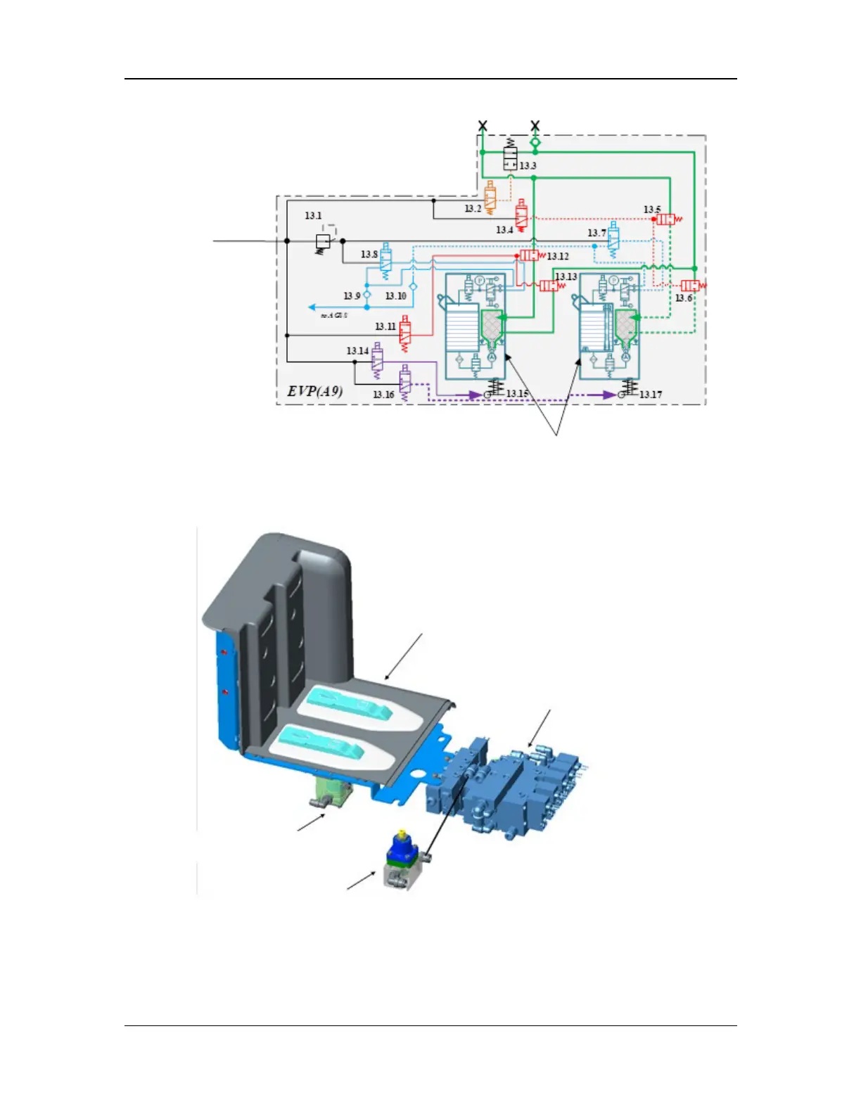
Figure 23 Pneumatic diagram of the electronic vaporizer manifold assembly
The electronic vaporizer manifold assembly consists of the electronic vaporizer manifold,
pneumatically-controlled locks (13.15 and 13.17), pressure regulator (13.1), and control module.
The structural diagram is shown below.
Figure 24 Structural diagram of the electronic vaporizer manifold assembly
Drive gas
Gas inlet
Gas outlet
Electronic vaporizer
Electronic vaporizer manifold
Electronic vaporizer control module
Pneumatically-controlled lock
Pressure regulator

Table of Contents

Other manuals for Mindray A8

Questions and Answers:

Question and Answer IconNeed help?

Do you have a question about the Mindray A8 and is the answer not in the manual?

Mindray A8 Specifications

General IconGeneral
BrandMindray
ModelA8
CategoryMedical Equipment
LanguageEnglish

Related product manuals