6-29
1) Zero
Remove the two protection caps from the LOW PRESSURE (–) and (+) ports. Select Low
Pressure > Zero > OK. The pressure displayed is 0.00 cmH2O.
Note 1: Zero the pressure of the calibration device before each pressure calibration.
Disconnect all pipelines from the calibration device before zeroing.
Note 2: When the device is not in use, install protection caps on all ports of the device to
prevent dust from entering and damaging the sensors.
Drive gas connection: The calibration gas is compressed O2.
Preparations before calibration: Enter the standby mode, opened the O2 cell door, verify that
the O2 cell holder and O2 cell are removed, set the auto/manual switch to Manual, and then
remove the circuit absorber canister, bypass assembly, and patient circuit in turn. Set the
auto/manual switch to Auto and turn off all flow regulators.
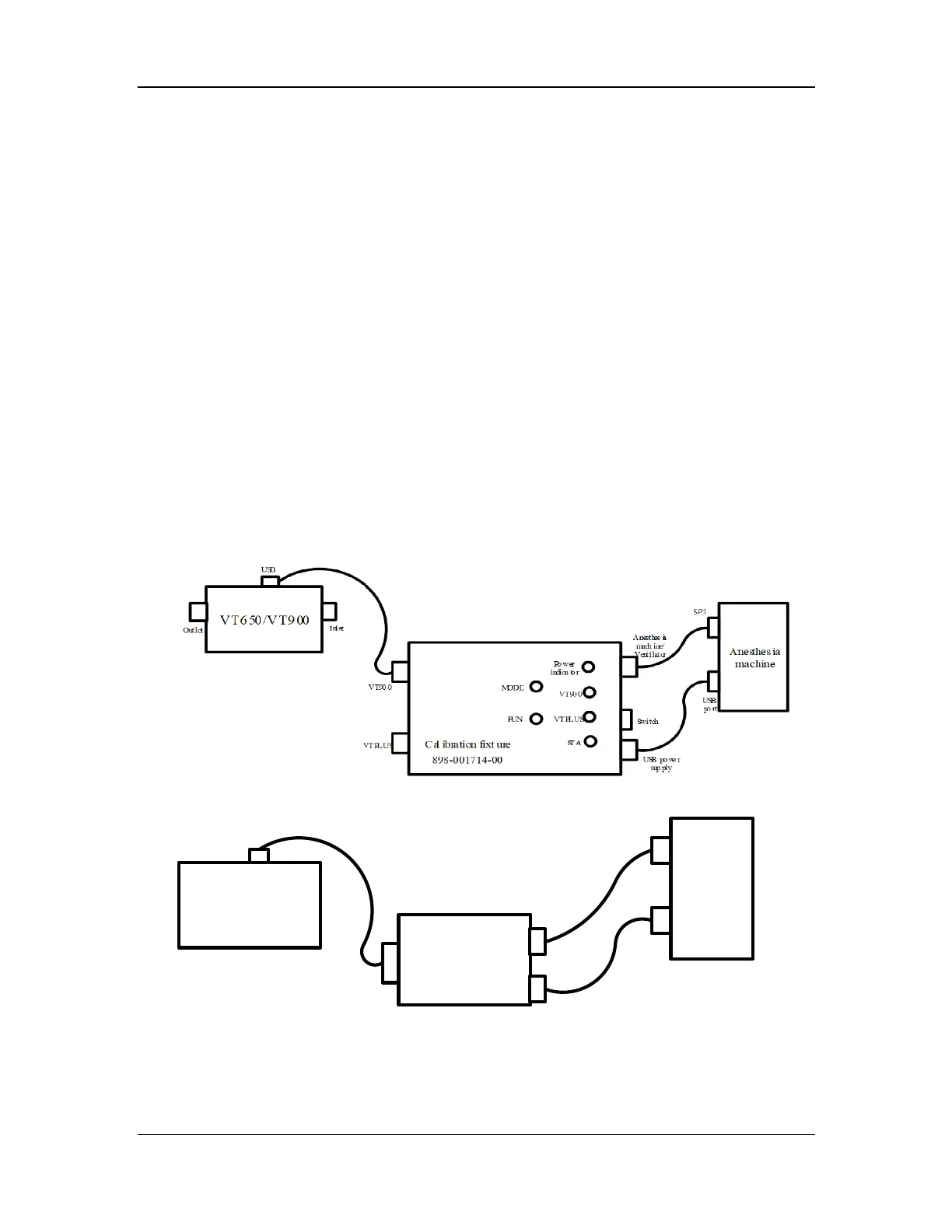
Calibration communication connection: If VT900 is used for calibration, connect the UBS port of
VT900 to the calibration port of the anesthesia machine through a calibration fixture according
to Figure 1; or replace VT900 with VT Plus for calibration as shown in Figure 1; or use VT Plus for
calibration as shown in Figure 2.
Connect the communication cable as shown in Figure 1 and turn on the calibration fixture. You
can switch the calibration device to VT Plus or VT900 through MODE on the calibration fixture.
When the calibration device is switched to VT Plus or VT900, the corresponding indicator is
steady on. When the calibration device is switched to VT900, set the system to the low pressure
measurement mode, press FUN and switch to Remote Control.
Figure 1 Calibration communication connection of VT900
Anesthesia
machine
Cal ibration fixt ure
0631-TF 08
U S B p o rt
U S B p o rt
C al ib r at io n por t
V T P lu s
COM
Figure 2 Calibration communication connection of VT Plus
Calibration pipeline connection (no auxiliary pressure): Mount the pressure calibration test
fixture (PN: 115-077270-00) to the circuit adapter block in place. Use a three-way silicone tube
to connect the two ports of the pressure calibration test fixture (as shown in Figure 3.1).