EasyManuals Logo

Mindray A9 Service Manual

Mindray A9
424 pages
To Next Page IconTo Next Page
To Previous Page IconTo Previous Page
Page #309 background imageLoading...
Page #309 background image
8-9
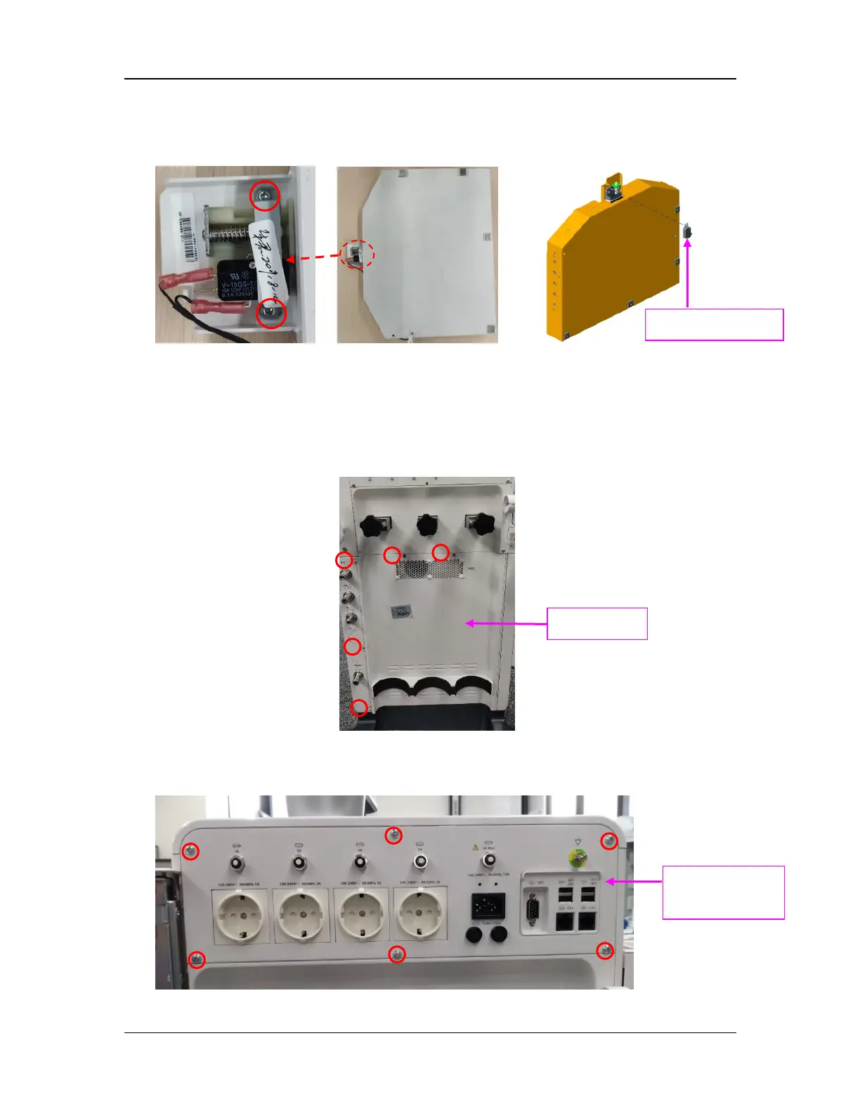
8.12.2 Remove the VE Mounting Box In-Position Switch
Remove the two screws with the Phillips screwdriver, remove the protection cap, disconnect the
plug, and then pull out the in-position switch.
8.13 Pre-disassembly (Disassemble Housings and Some System
Parts)
8.13.1 Open the Service Door
Remove the five screws from the service door with the Phillips screwdriver to open the door.
8.13.2 Remove the Auxiliary Output Assembly
Remove the six screws from the auxiliary output assembly with the Phillips screwdriver to
remove the assembly and disconnect 4 cables.
Auxiliary output
assembly
Service door
In-position switch

Table of Contents

Other manuals for Mindray A9

Questions and Answers:

Question and Answer IconNeed help?

Do you have a question about the Mindray A9 and is the answer not in the manual?

Mindray A9 Specifications

General IconGeneral
TypeAnesthesia Workstation
Integrated Gas AnalysisYes
Backup BatteryYes
Operating Temperature10°C to 40°C
Storage Temperature-20°C to 55°C
Battery TypeLithium-ion
Ventilation ModesVolume Control, Pressure Control, SIMV, Manual Ventilation
DisplayTouchscreen
Patient MonitoringECG, SpO2, NIBP, EtCO2, Temperature
ConnectivityEthernet, USB
PortabilityMobile (with wheels)
Battery LifeMinimum 90 minutes (typical)
AltitudeUp to 3000 meters
Power Supply100-240 VAC, 50/60 Hz
Charging TimeApproximately 4 hours
StorageInternal storage for patient data and system logs
Supported LanguagesMultiple languages
CertificationsCE, FDA

Related product manuals