5-8
5.6.3 Accuracy Confirmation Test
1. Connect the O2 supply.
2. Adjust the auto/manual switch to Manual and APL valve to SP.
3. Connect the Y-piece in the breathing circuit to the leak test port, and the other two ends to
the expiratory and inspiratory ports of the circuit. Connect a manual bag to the bag arm port.
4. Open the Backup AIR/O2 door and turn on the backup flowmeter.
5. Adjust the O2 knob of the backup flowmeter according to the table below. Verify that the
readings of the backup total flowmeter and the glass tube flowmeter on the left of the screen
meet the following requirements:
Adjust the backup flowmeter.
Reading on the glass tube
flowmeter
Flow displayed on the
left of the screen
Adjust the O2 knob of the backup
flowmeter.
5.7 Electronic Vaporizer Test (A9 only)
5.7.1 Vaporizer Monitoring Function Test
5.7.1.1 Monitoring the Heating Foil Temperature
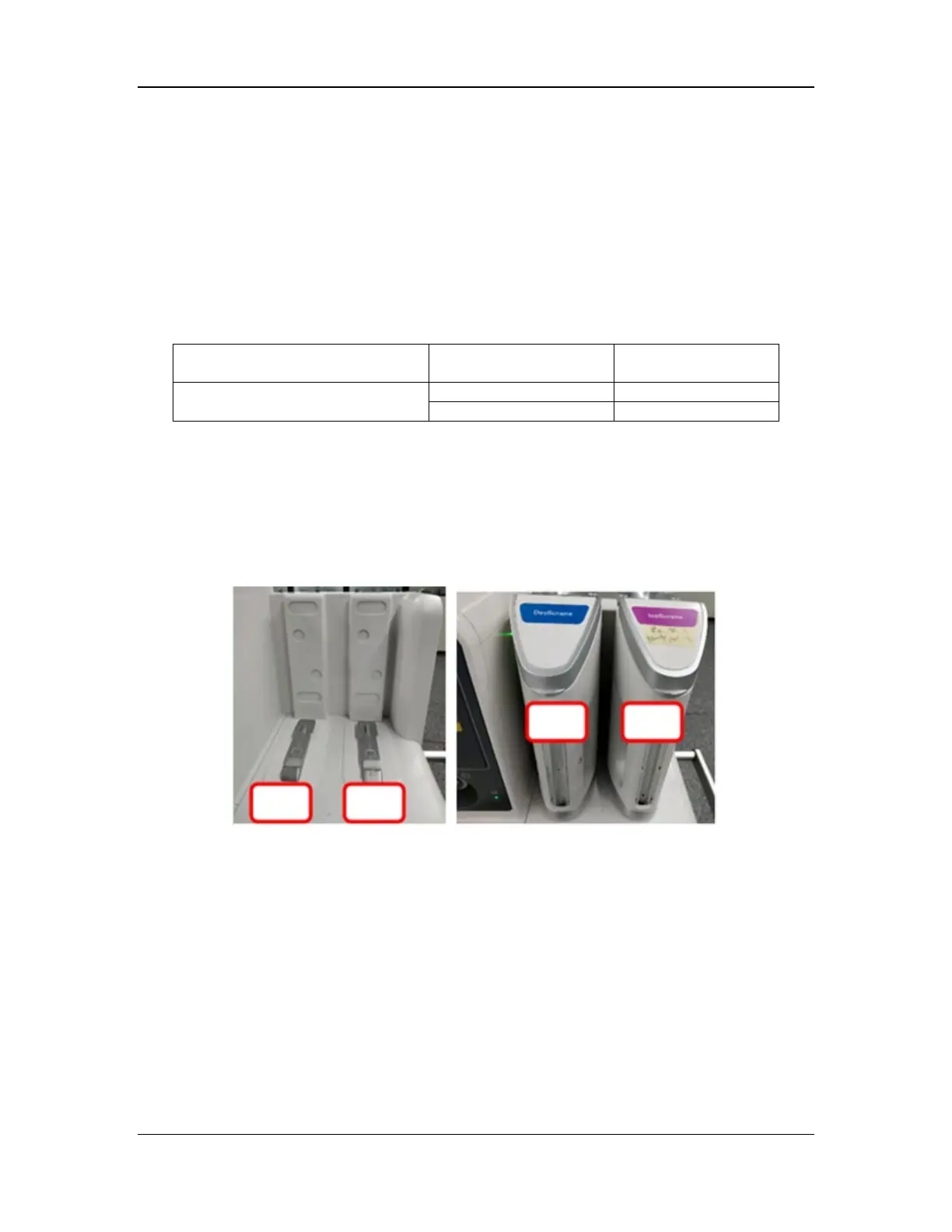
1. Install the vaporizer in canister position 1 of the vaporizer manifold.
2. Select Setup > Service > Diagnostic Tests > Vaporizer 1 Tests to access the vaporizer test
screen.
3. Verify that the difference between the displayed values of Heating Temp Sensor 1 and
Heating Temp Sensor 2 does not exceed 5°C.
4. Set Heating Foil to On. Verify that the displayed values of Heating Temp Sensor 1 and
Heating Temp Sensor 2 gradually increase, and are held at fixed values after about 5
minutes. The hold value of a sevoflurane or isoflurane vaporizer is 47±3°C. The hold value
of a desflurane vaporizer is 37±3°C.
5.7.1.2 Monitoring the Drive Gas Pressure
1. Install the vaporizer in canister position 1 of the vaporizer manifold.
2. Select Setup > Service > Diagnostic Tests > Vaporizer 1 Tests to access the vaporizer test
screen.