2-80
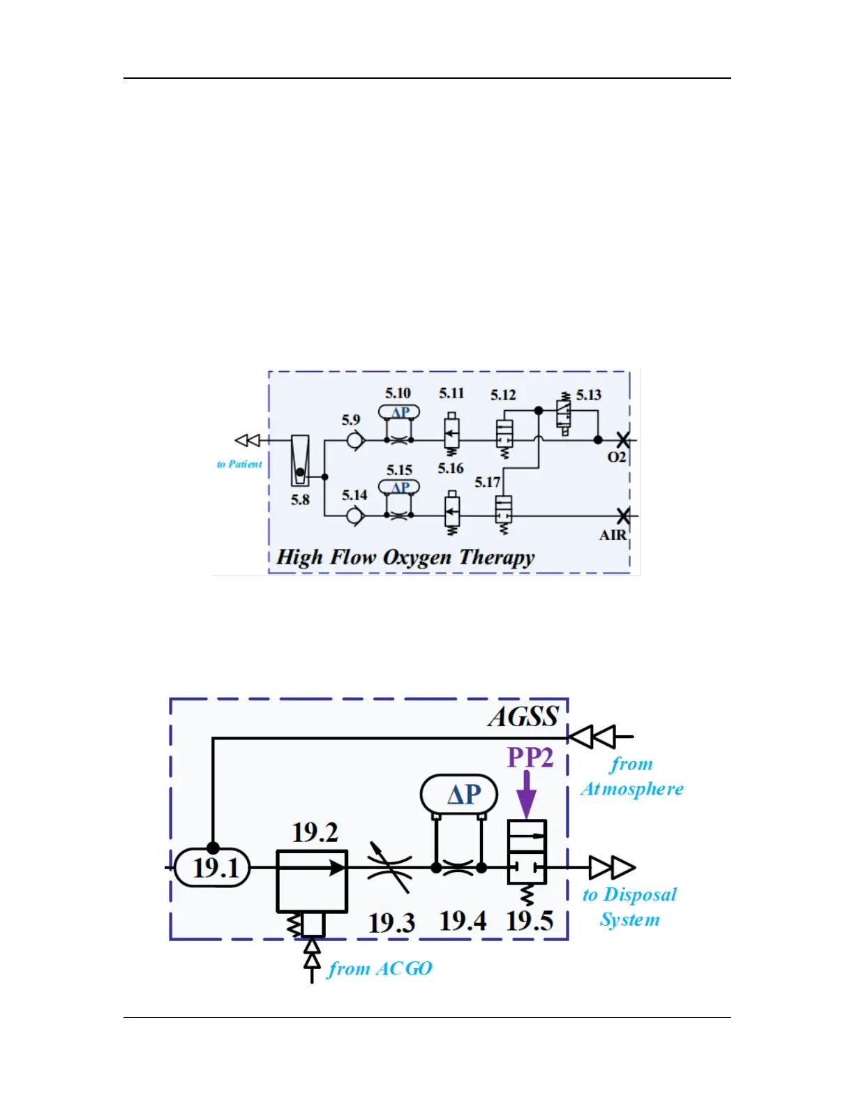
2.3.6.1 High-Flow O2 Supply Assembly
The high-flow O2 supply assembly can provide patients with O2 and air at adjustable
concentration. The input includes O2 and air obtained after pressure adjustment by the pipeline
gas inlet assembly. The flows of the two gases are adjusted through independent proportional
valves (5.11 and 5.16) and measured through independent differential pressure sensors (5.10 and
5.15). After the O2 and air are mixed, the flow is indicated by the mechanical float flowmeter
(5.8). To reduce the risk of proportional valve failure, the pilot control switch valves (5.12 and
5.17) are added to the front of the proportional valves in the two branches to ensure safety in case
of proportional valve failure. The maximum flow of the proportional valves is increased to 60
L/min, and the designed overall output flow of the module is 100 L/min. The high-flow O2
supply assembly consists of the flow control module, high-flow O2 therapy flowmeter, and outlet
assembly, which are independent components installed in different positions of the system and
connected through PU tubes. The pneumatic diagram of the high-flow O2 supply assembly is
shown below.
Figure 38 Pneumatic diagram of the high-flow O2 supply assembly
2.3.7 AGSS Subsystem
The AGSS subsystem is connected to the breathing circuit and the hospital's negative pressure
suction system for waste gas scavenging of the anesthesia machine. It consists of the gas
reservoir assembly (19.1) and AGSS pneumatic block assembly.
Figure 39 Pneumatic diagram of the active AGSS