2-81
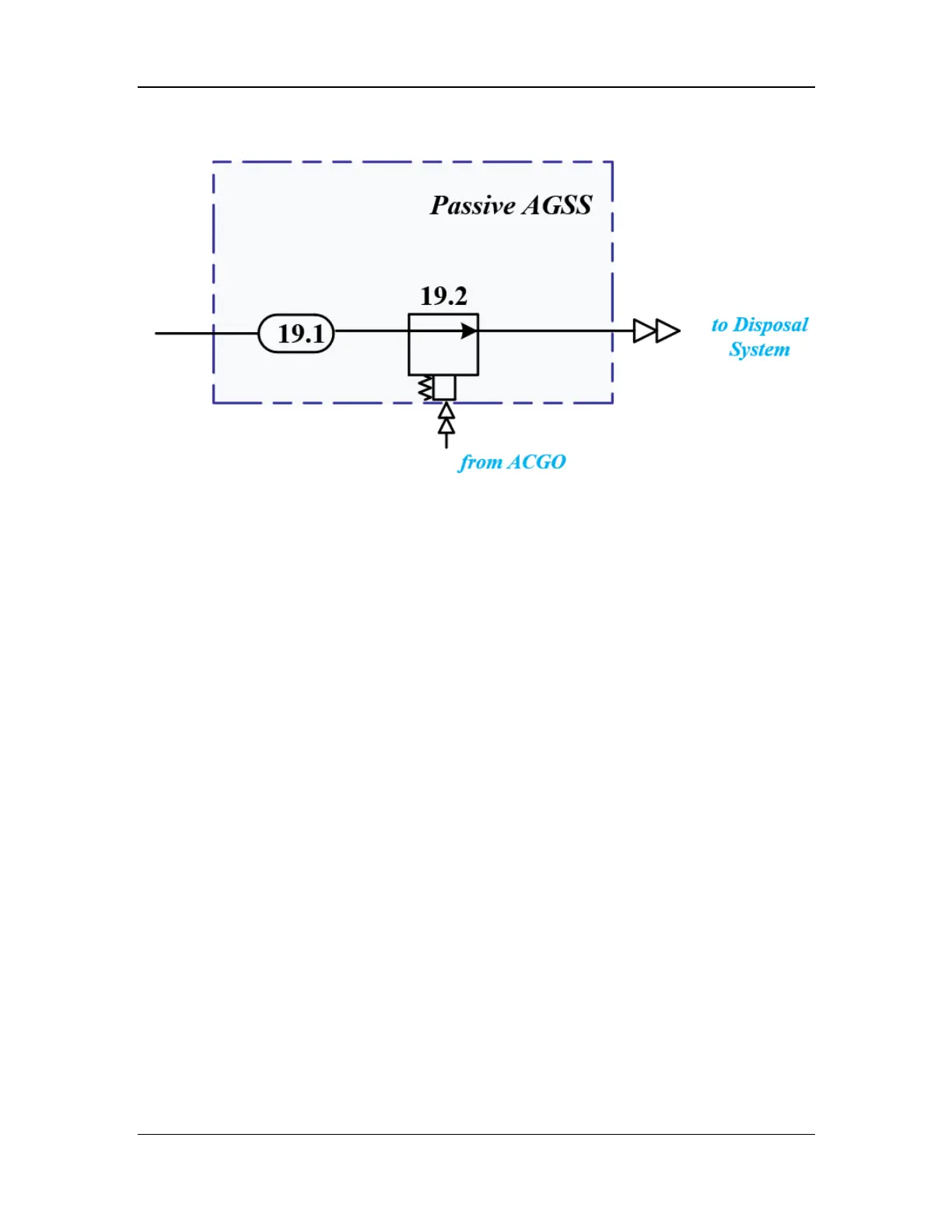
Figure 40 Pneumatic diagram of the passive AGSS
2.3.7.1 Gas Reservoir Assembly
The gas reservoir is used to prevent the anesthetic gas from overflowing out of the AGSS during
peak anesthetic gas scavenging of the anesthesia machine, and is used to receive and buffer the
exhausted gas and eliminate the noise generated by the breathing gas. The input of the gas
reservoir includes: drive gas from the anesthesia ventilator, PEEP limb gas from the anesthesia
ventilator, returned sample gas of the gas module, and excess gas from the breathing system.
Gas reservoir assemblies are classified into active and passive AGSS gas reservoir assemblies
depending on whether there is an overfill port. The active AGSS gas reservoir assembly is used to
pump waste gas from the anesthesia machine with a negative pressure source of the hospital. The
passive AGSS gas reservoir assembly is used to passively exhaust waste gas to air without a
negative pressure source. The negative pressure source is the key to distinguishing between
active and passive AGSS gas reservoir assemblies.
For the active AGSS gas reservoir assembly, the outlet, namely, the waste gas scavenging port, is
connected to the AGSS pneumatic block assembly through a silicone tube. When positive or
negative pressure different from the atmospheric pressure is generated in the AGSS gas reservoir,
gas intake or exhaust is performed to ensure the pressure balance. In addition, when the negative
pressure source pumps the waste gas, it is ensured that the inlet pressure is higher than a certain
value and the induced flow is lower than a certain value. These are key factors in the design of
gas reservoir assemblies.
The active AGSS gas reservoir assembly consists of three parts: AGSS inlet gas reservoir, AGSS
pump box, and AGSS airway. The AGSS pump box is connected to the pneumatic block through
a silicone tube. After the waste gas enters the gas reservoir, it is pumped to the AGSS pneumatic
block assembly under the action of the gas reservoir. The AGSS gas reservoir is connected to the
work surface through the bottom metal sheet. The overfill port is connected to the metal sheet
through a silicone part. Exchange with the outside air is enabled through the meshes of the rear
cover plate. The structural diagram of the active AGSS gas reservoir assembly is shown below.