2 System Configuration
[Part 2] System Configuration and Setting (CR750-Q/CR751-Q series,
CRnQ-700 series)
2. System Configuration
2.1. Components
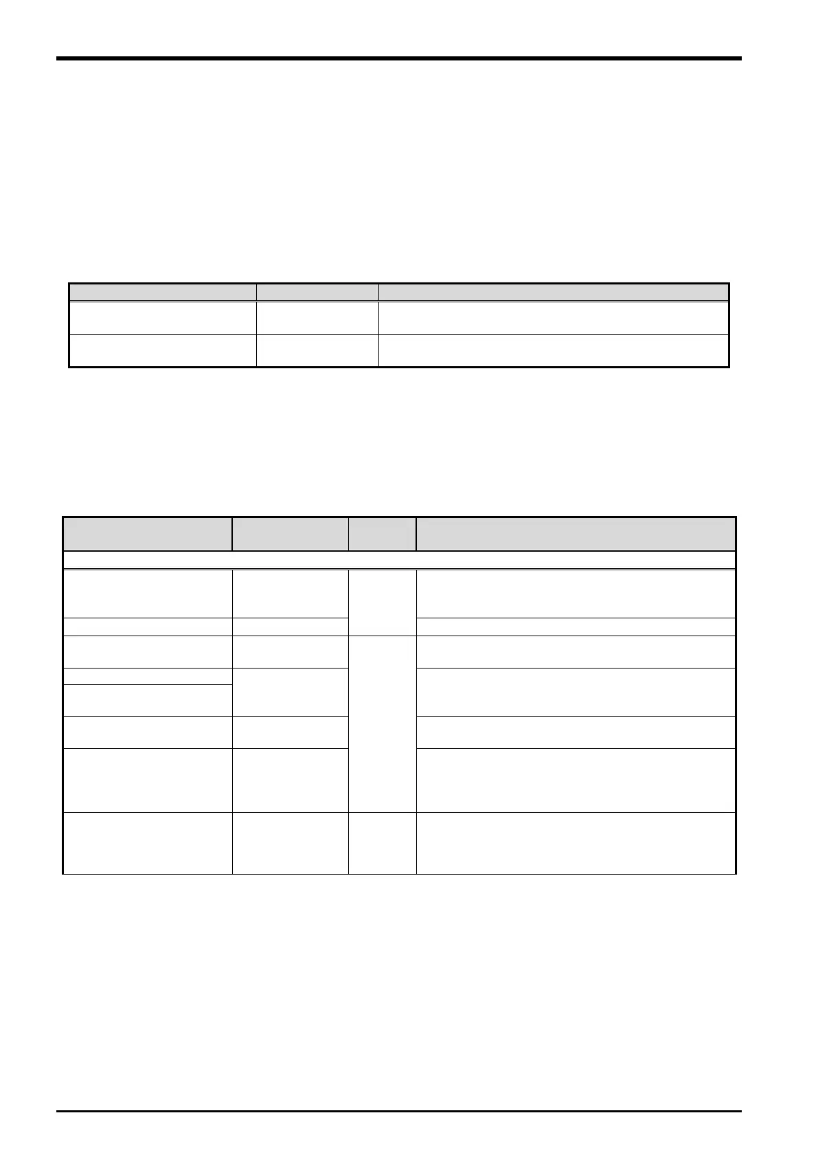
2.1.1. Robot controller enclosure products
The product structure of the tracking functional relation enclosed by the robot controller is shown in the
Table 2−1.
Table 2
−1 List of Configuration in the tracking functional-related product
Tracking Function
INSTRUCTION MANUAL
This manual is included in instruction-manual CD-ROM
attached to the product.
Please refer to "12 Sample Robot Programs" for the
sample robot program.
2.1.2. Devices Provided by Customers
When configuring the system, the customers must have certain other devices in addition to this product. The
table below shows the minimum list of required devices. Note that different devices are required depending
on whether conveyer tracking or vision tracking is used. Please refer to “Table 2−2 List of Devices Provided
by Customers (Conveyer Tracking)” and “Table 2−3 List of Devices Provided by Customers (Vision
Tracking)” for further details.
Table 2
−2 List of Devices Provided by Customers (Conveyer Tracking)
Name of devices to be
provided by customers
Model Quantity Remark
or
1
−
(1)
Used to confirm that workpieces are gripped
correctly. Provide as necessary.
See the Remark
column
Different models are used depending on the robot
used. Check the robot version and provide as
(CRnQ-700/CRnD-700 series controller)
Provide as necessary.
−
This is a jig with a sharp tip that is attached to the
mechanical interface of the robot arm and used for
calibration tasks. It is recommended to use the jig if
high precision is required.
Q173DPX
More than
1
Manual pulser input unit for motion controller
[*]This unit cannot be connected with two or more
robot CPU. Please prepare for unit necessary in each
2-6 Components

 Loading...


