5 Connection of Equipment
5.2.3. Connection of Photoelectronic Sensor
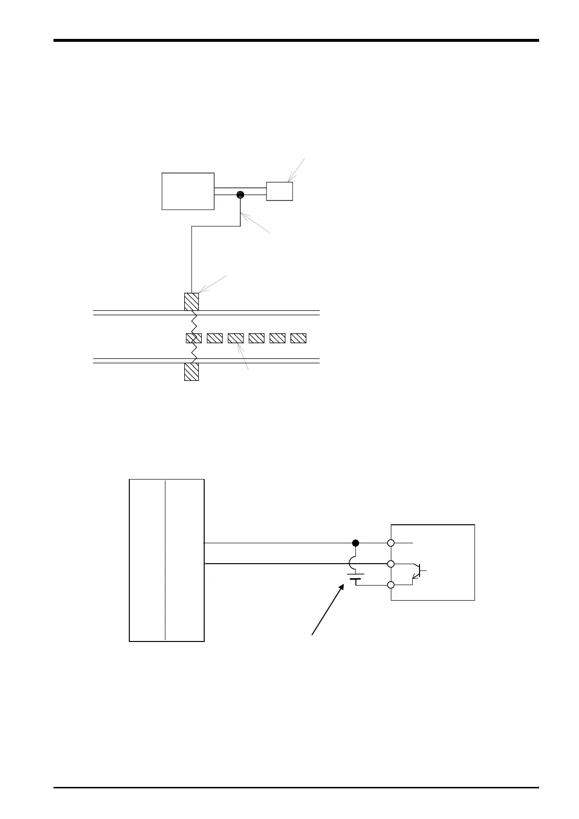
If a photoelectronic sensor is used for detection of workpieces, connect the output signal of the
photoelectronic sensor to a tracking enable signal of the Q173DPX unit.
In this section, a connection example where the photoelectronic sensor signal is connected to the tracking
enable signal is shown in “
Figure 5
−8 Photoelectronic Sensor Arrangement Example
Figure 5
−9 Photoelectronic Sensor Connection Example (6th General Input Signal is Used)
Input circuit external power supply
Connects to the tracking enable signal of the Q173DPX unit.
A4
TREN1+
B4
TREN1-
sensor
(Example of 3 line type)
Note) The external power supply and photoelectric sensor must be
prepared
Connection of Equipment 5-23

 Loading...


