10 Connection of Equipment
10. Connection of Equipment
This section explains how to connect each of the prepared pieces of equipment.
10.1. Preparation of Equipment
Prepare equipment by referring to “Table 2−2 List of Devices Provided by Customers (Conveyer Tracking)”
to construct a conveyer tracking system and “Table 2−3 List of Devices Provided by Customers (Vision
Tracking)” to construct a vision tracking system.
10.2. Connection of Equipment
This section explains how to connect each of the prepared pieces of equipment.
10.2.1. Connection of Conveyer Encoder
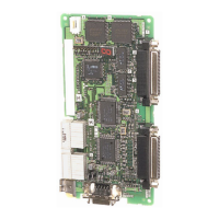
Wiring of the encoder for the conveyors and the encoder cable is shown in the "Figure 10−1” (CRnD-700
series) or “Figure 10−3” (CR750-D/CR751-D series). Those shows the connection between a Expansion
serial interface card connector and an encoder.(The cable uses E6B-2-CWZ1X (by OMRON).)
The a maximum of two encoders for the conveyors are connectable as standard specification. A total of 8
signal wires are required for the connection for the power supply (+ and - terminals) and the + and -
terminals of the differential encoders' A, B and Z phases. Refer to the instruction manual of the encoders to
be used and connect the signal wires correctly. Note that shielded wires (SLD) should be connected to the
ground of the controller and system.
10-38 Preparation of Equipment

 Loading...


