10 Connection of Equipment
CH1
CNUSR11 6
CNUSR12 6
CNUSR13 3
CNUSR13 4
CNUSR13 5
CNUSR13 6
CNUSR13 8
CNUSR13 10
Blue(+0V)
Black
Black/Red stripe
White
White/Red stripe
Orange
Orange/Red stripe
SLD
+5V power
supply unit
Brown(+5V)
Ferrite core
Encorder
Blue(+0V)
Black
Black/Red stripe
White
White/Red stripe
Orange
Orange/Red stripe
SLD
+5V power
supply unit
Brown(+5V)
Ferrite core
Encorder
<CR751-D
connector>
<CR750-D
connector>
CH2
CNUSR2 15
CNUSR2 40
CNUSR2 21
CNUSR2 46
CNUSR2 22
CNUSR2 47
CNUSR2 23
CNUSR2 48
CH1 SG
SG
LAH1
LAL1
LBH1
LBL1
LZH1
LZL1
CH2 SG
SG
LAH2
LAL2
LBH2
LBL2
LZH2
LZL2
CH1
CNUSR1 28
CNUSR1 33
CNUSR1 21
CNUSR1 46
CNUSR1 22
CNUSR1 47
CNUSR1 23
CNUSR1 48
CH2
CNUSR2 15
CNUSR2 40
CNUSR2 21
CNUSR2 46
CNUSR2 22
CNUSR2 47
CNUSR2 23
CNUSR2 48
Terminal
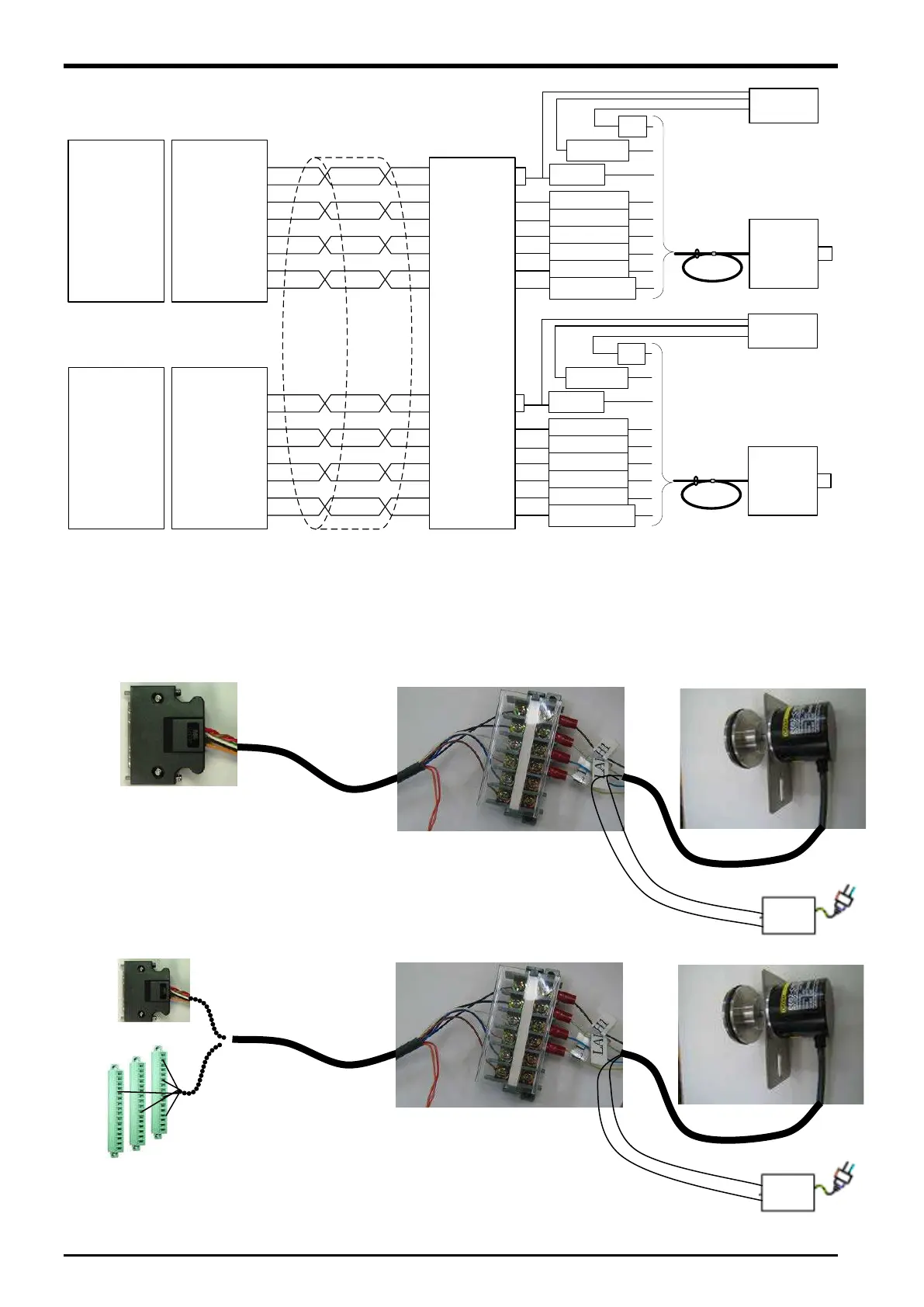
Figure 10
−3 Wiring of the encoder for conveyors and encoder cable (CR750-D/CR751-D series controller)
Refer to "Table 21−3 Connectors: CNENC/CNUSR Pin Assignment" with pin assignment of connector
CNUSR.
The wiring example by the thing is shown below.
(Please note that the connector shape is different depending on the controller. )
Figure 10
−4 Wiring example (CR751-D series controller)
Figure 10
−5 Wiring example (CR750-D series controller)
電源
電源
10-40 Connection of Equipment

 Loading...


