13 Calibration of Conveyer and Robot Coordinate Systems (
“
A1
”
program)
13. Calibration of Conveyer and Robot Coordinate Systems (“A1” program)
This chapter explains the tasks carried out by using “A1” program.
* “A1” program contains operations required for both conveyer tracking and vision tracking.
Calibration of a conveyer refers to determining the movement direction of the conveyer in the robot
coordinate system and the amount of movement of the robot per encoder pulse. This amount of movement
is stored in the robot’s status variable “P_EncDlt.”
“A1” Program performs specified tasks and automatically calculates the amount of movement of the robot
per encoder pulse mentioned above.
The procedures of operations specified by “A1” program and items to be confirmed after the operations are
explained below.
Please refer to “Detailed Explanations of Functions and Operations” for the steps involved in each operation.
Please monitor status variable “M_Enc(1)" to “M_Enc(8)" before it works, rotate the encoder, and confirm
the value changes.
13.1. Operation procedure
1) Mount a calibration jig on the mechanical interface of a robot. Connect a personal computer on which
RT ToolBox2(option) is installed to the robot controller.
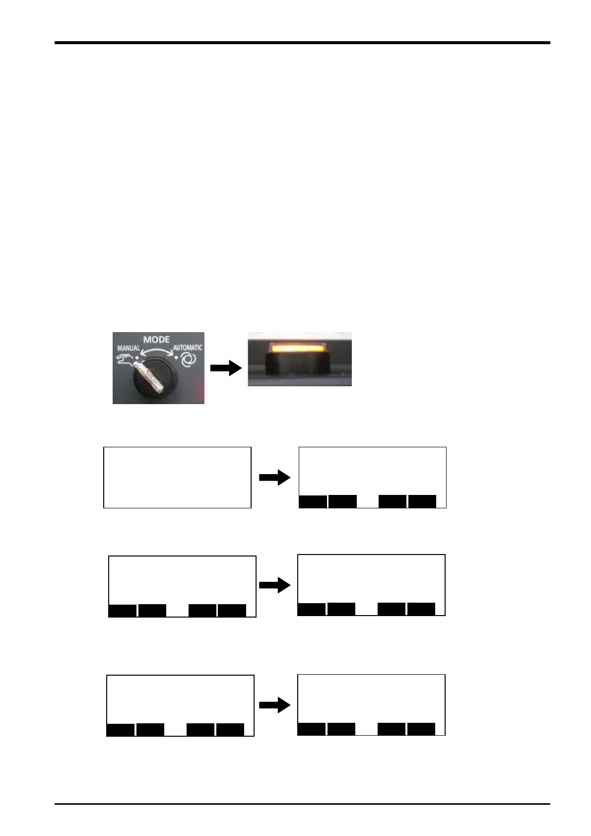
2) Set the controller mode to "MANUAL".
Set the T/B to "ENABLE".
3) Press one of the keys (example, [EXE] key) while the <TITLE> screen is displayed. The <MENU>
screen will appear.
4) Select "1. FILE /EDIT" screen on the <MENU> screen.
5) Press the arrow key, combine the cursor with the program name "A1" and press the [EXE] key.
Display the <program edit> screen.
O
P
T
B
:
:ENABLE
★
Lamp lighting
T
B
2 '# tracking robot‐conveyor calibra
4 '# Create/version : 2006.04.21 A1
1 '## Ver.A1 ########################
<FILE/EDIT> 1/ 20Rem 136320
<FILE/EDIT> 1/ 20Rem 136320
COPYRIGHT (C) 2011 MITSUBISHI ELEC
TRIC CORPORATION ALL RIGHTS RESE
Operation procedure 13-49

 Loading...


