14 Calibration of Vision Coordinate and Robot Coordinate Systems (
“
B1
”
program)
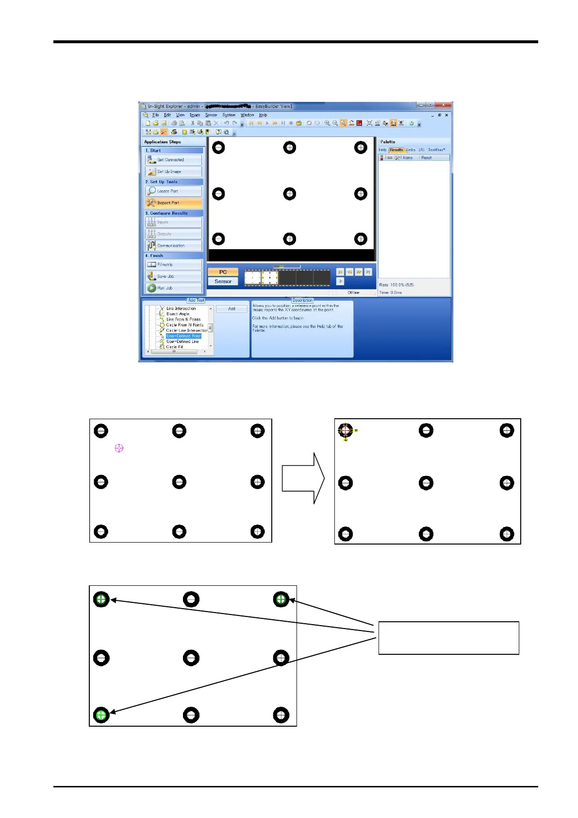
4) End [Live Video] of In-Sight Explorer, and select [Inspect Part] button of “Application Steps”.
5) Select [Geometry Tools] - [User-Defined Point] in “Add tool”.
Figure 14
−4 Screen of In-Sight Explorer from which calibration seat is taken picture
6) Click [Add] button. Then, the cross sign enclosed with circle on the screen is displayed.
Move it to the mark of the calibration seat, and click [OK] button.
7) Specify the “User-Defined point” in three points or more repeating the above-mentioned work.
The example of specifying
these three points is shown.
Tasks 14-59

 Loading...


