16 Teaching and Setting of Adjustment Variables (
“
1
”
Program)
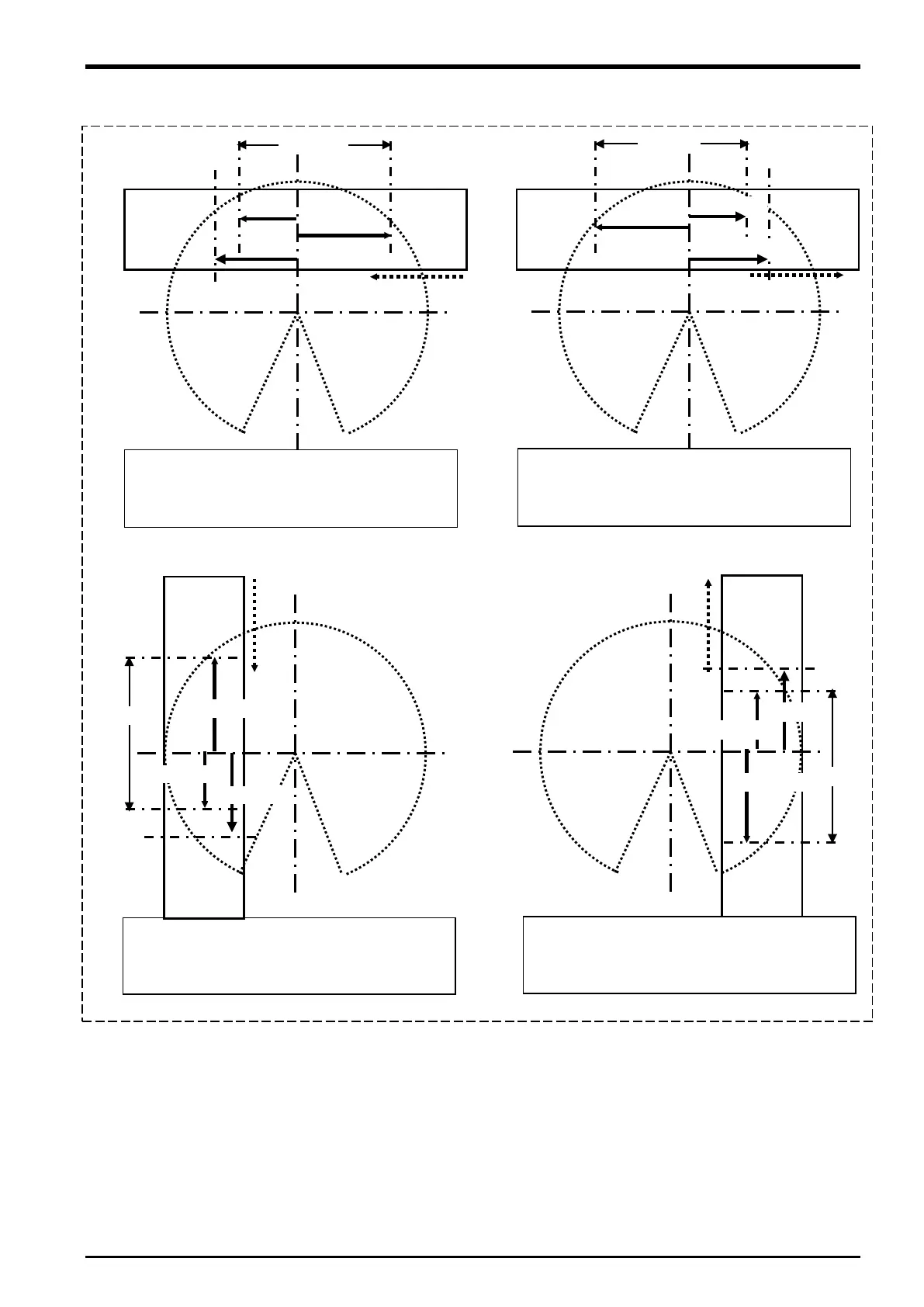
Figure 16
−3 Diagram of Relationship between Adjustment Variables “PRNG” and “PTN” in the Program
When the conveyer is placed in front of the
robot
and the workpiece moves from the
(= the X coordinate of PTN is “1”)
,Z)=(+500,+300,+400)
Workpiece
movement direction
When the conveyer is placed on the left side
of the robot and the workpiece move
the front to rear (= the X coordinate of PTN is
Workpiece
movement direction
When the conveyer is placed on the right side
of the robot and the workpiece move
the rear to front (= the X coordinate of PTN is
Workpiece
movement direction
When the conveyer is placed in front of the
robot and the workpiece moves from the lef
to right (= the X coordinate of PTN is “2”)
PRNG: (X,Y,Z)=(+300,+100,+200)
Workpiece
movement direction
Setting of adjustment variables in the program 16-83

 Loading...


