4
I/O NUMBER ASSIGNMENT
4.3 Installing Extension Base Units and Setting the Number of Stages
4
- 9
1
Overview
2
Performance
Specification
3
Sequence Program
Configuration and
Execution Conditions
4
I/O Nunber Assignment
5
Memories and Files
Handled by CPU Module
6
Functions
7
Communication with
Intelligent Function
Module
8
Parameters
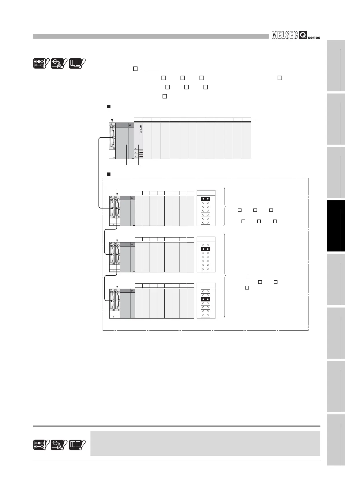
(d) Layout for use of AnS series compatible extension base units
(QA1S6 B)
Note4.1
Note1
When using the Q5 B/Q6 B/Q6 RB together with the QA1S6 B in a system,
connect all of the Q5 B/Q6 B/Q6 RB close to the main base unit and then
connect the QA1S6 B after them.
Note1
Diagram 4.8 Layout for use of AnS series compatible extension base units
Basic
Process Redundant
Note4.1Note4.1 Note4.1
The AnS series compatible extension base units are not available for the Basic model QCPU,
Process CPU and Redundant CPU.
Basic
Process Redundant
Note4.1Note4.1 Note4.1
Power supply
module
CPU module
Extension 1
Main base unit
Slot number
CPU 0 1 2 3 4 5 6 7 8 9 10 11
12 13 14 15 16 17 18 19
Extension 2
20 21 22 23 24 25 26 27
Extension 3
28 29 30 31 32 33 34 35
Extension base unit
Q312B
Q68B
QA1S68
QA1S68
Extension base unit for
mounting module
corresponding to the AnS Series
(QA1S6 B is connected to
the end of Q5 B/Q6 B or
QA1S6 B.)
Extension base unit for
mounting module corresponding
to the Q Series
(Q5 B/Q6 B/Q6 RB is
connected to the main base unit
or Q5 B/Q6 B/Q6 RB.)
 Loading...

