6
FUNCTIONS
6.11 Monitor Function
6.11.1 Monitor condition setting
6
- 46
1
Overview
2
Performance
Specification
3
Sequence Program
Configuration and
Execution Conditions
4
I/O Nunber Assignment
5
Memories and Files
Handled by CPU Module
6
Functions
7
Communication with
Intelligent Function
Module
8
Parameters
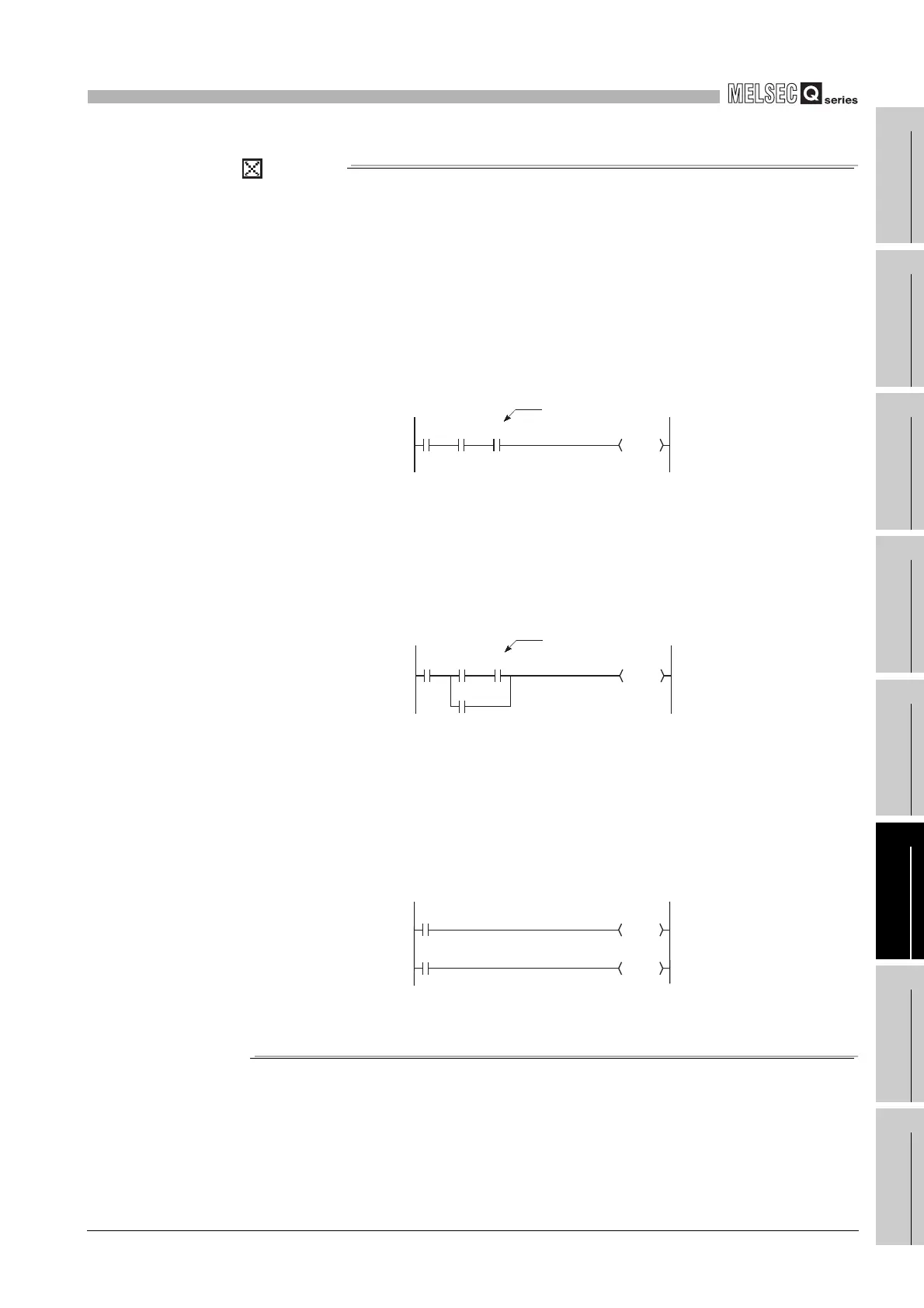
POINT
1 . If a step between the AND/OR blocks is specified as a monitor condition,
monitor data is sampled when the status previous to execution of the
specified step is specified by the LD instruction. The monitor timing depends
on the step specified as a monitor condition. The following shows examples of
monitoring when the Step 2 is ON (Step No. [ 2] = <ON>).
• When the Step 2 is connected by the AND instruction:
In Diagram 6.28, the monitor execution condition is established when
both "X0" and "X1" are ON.
• When the Step 2 is connected between the AND/ON blocks:
In Diagram 6.29, the monitor execution condition is established when
"X1" is ON. Whether "X0" is ON or OFF, it does not affect the monitor
execution condition.
• If the beginning of a ladder block not at Step 0 is specified in Step No. as
a detailed condition, monitor data is collected when the execution status
of the instruction immediately before execution becomes the specified
status. If (Step No. [ 2] = <ON>) is specified in the following ladder,
monitor data is collected when OUT Y10 turns ON.
2 . Be sure to set the condition of the step set as step No.0 to "Always".
Diagram 6.28 When the Step2 is connected by the AND instruction
Diagram 6.29 When the Step 2 is connected between the AND/ON blocks
Diagram 6.30 When the beginning of a ladder block not at Step 0 is specified in Step No.
0
X0 X1 X2
Ladder mode List mode
Y20
0LD X0
1 AND X1
2 AND X2
3 OUT Y20
Step 2
0
Y20
X0 X1 X2
X3
0LD X0
1LD X1
2 AND X2
3OR X3
4 ANB
5 OUT Y20
Step 2
Ladder mode List mode
0
Y10
X0
2
Y11
X1
Ladder mode List mode
0LD X0
1 OUT Y10
2LD X1
3 OUT Y11
 Loading...

