9
DEVICE EXPLANATION
9.1 Device List
9
- 4
9
Device Explanation
10
CPU Module Processing
Time
11
Procedure for Writing
Program to CPU Module
AppendicesIndex
* 1 : For the timer, retentive timer, and counter, bit devices are used for the "contact" and the "coil", and
the word device is used for the "present value".
* 2 : The actual number of usable points varies according to the intelligent/special function module
Note9.1
.
For details regarding the buffer memory's "number of points", refer to the Intelligent/Special
Function Module Manual.Note1
* 3 : Can be changed in the PLC parameter dialog box of GX Developer. (Except the input, output, step
relay, link special relay and link special register.) ( Section 9.2)
Other
Bit
devices
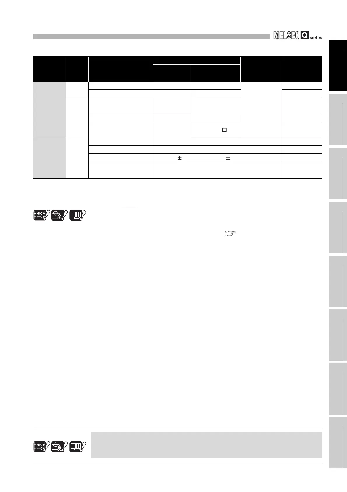
SFC block device 320 points BL0 to 319
Unchangeable
Section 9.11.1
SFC transition device 512 points TR0 to 511 Section 9.11.2
--
Network No.
designation device
256 points J1 to 255 Section 9.11.3
I/O No. designation device -- U0 to FF Section 9.11.4
Macro instruction
argument device
--
VD0 to
Section 9.11.5
Constants --
Decimal constants K-2147483648 to 2147483647 Section 9.12.1
Hexadecimal constants H0 to FFFFFFFF Section 9.12.2
Real number constants
E 1.17550 - 38 to E 3.40282 + 38
Section 9.12.3
Character string
constants
"ABC" and "123" Section 9.12.4
Note1
Table9.2 Device List(Continued)
Class Type Device Name
Default Values
Parameter
Designated
Setting Range
Reference
Section
Number of
Points
*3
Range Used
Basic
Process Redundant
Note9.1 Note9.1
Note9.1
The Basic model QCPU, Process CPU and Redundant CPU do not support the special function
modules.
Basic
Process Redundant
Note9.1Note9.1
Note9.1
 Loading...

