App
- 45
Appendix 2 Special Register List
APPENDICES
TableApp.20 Special register
Number Name Meaning Explanation
Set by
(When set)
Corres-
ponding
ACPU
D9
Corresponding
CPU
SD254
MELSECNET/
10.
MELSECNET/H
information
Number of
modules installed
• Indicates the number of mounted MELSECNET/10 modules or
MELSECNET/H modules.
S (Initial) New
SD255
Information from 1st module
I/O No.
• Indicates I/O number of mounted MELSECNET/10 module or
MELSECNET/H module
SD256
Network
No.
• Indicates network No. of mounted MELSECNET/10 module or
MELSECNET/H module
SD257
Group
number
• Indicates group No. of mounted MELSECNET/10 module or
MELSECNET/H module
SD258
Station
No.
• Indicates station No. of mounted MELSECNET/10 module or
MELSECNET/H module
SD259
Standby
informa-
tion
• In the case of standby stations, the module number of the standby
station is stored. (1 to 4)
QnA
Qn(H)
QnPH
QnPRH
SD260
to
SD264
Information from
2nd module
• Configuration is identical to that for the 2nd module.
SD265
to
SD269
Information from
3rd module
• Configuration is identical to that for the 3rd module.
SD270
to
SD274
Information from
4th module
• Configuration is identical to that for the 4th module.
SD280 CC-Link error
Error detection
status
1) When Xn0 of the mounted CC-Link module turns ON, the bit of the
corresponding station turns to 1 (ON).
2) When either Xn1 or XnF of the mounted CC-Link module turns OFF, the
bit of the corresponding station turns to 1 (ON).
3) Turns to 1 (ON) when communication between the mounted CC-Link
module and CPU module cannot be made.
The above module Nos. n are in order of the head I/O numbers.
(However, the one where parameter setting has not been made is not
counted.)
S (Error) New
Qn(H)
QnPH
QnPRH
Rem
• When Xn0 of the mounted CC-Link module turns ON, the bit of the
corresponding station turns to 1 (ON).
• When either Xn1 or XnF of the mounted CC-Link module turns OFF, the
bit of the corresponding station turns to 1 (ON).
• Turns to 1 (ON) when communication between the mounted CC-Link
module and CPU module cannot be made.
S (Error) New QnA
SD290
Device
allocation
(Same as
parameter
contents)
Number of points
allocated for X
• Stores the number of points currently set for X devices
S (Initial) New
Rem
SD291
Number of points
allocated for Y
• Stores the number of points currently set for Y devices
SD292
Number of points
allocated for M
• Stores the number of points currently set for M devices
SD293
Number of points
allocated for L
• Stores the number of points currently set for L devices
SD294
Number of points
allocated for B
• Stores the number of points currently set for B devices
Rem
SD295
Number of points
allocated for F
• Stores the number of points currently set for F devices
SD296
Number of points
allocated for SB
• Stores the number of points currently set for SB devices
Rem
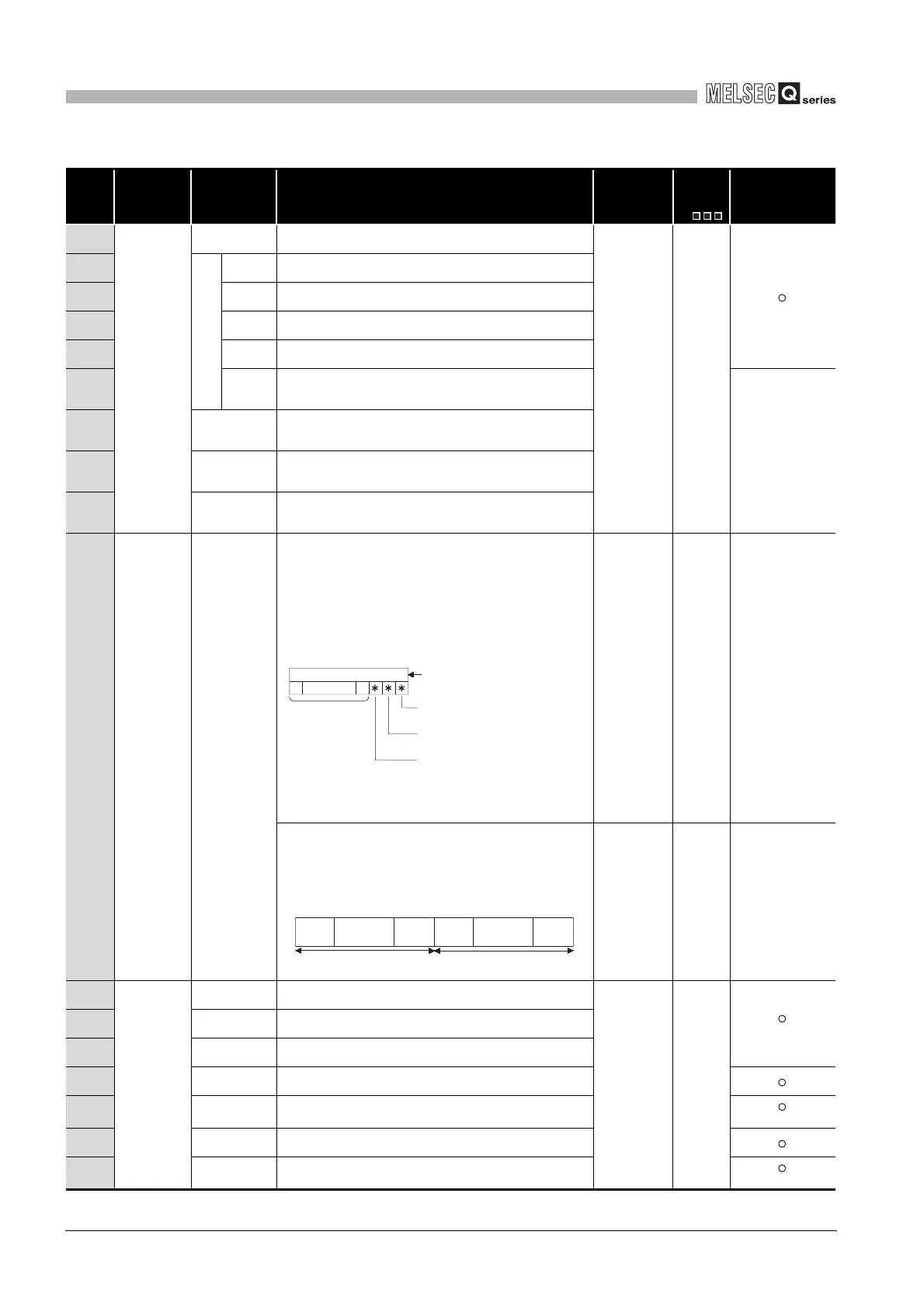
0000
to
0
12
3
4
15
14 to
(Not used)
(Bit number)
SFC block designation
present (1)/absent (0)
SFC step designation
present (1)/absent (0)
SFC transition designation
present (1)/absent (0)
tob15
Information of 2) Information of 1)
b9
8th
module
1st
module
tob8 b0
8th
module
1st
module
 Loading...

