MKS 937B Operation Manual
115
Dry all internal components and the sensor body
9
in a clean oven set at 150°C. The two ceramic
spacers,
4
and
7
, are slightly porous and will require longer drying time in the oven to drive off
the absorbed water.
12.2.4 Assembling the I-MAG Sensor
Wear gloves and assemble with clean tools.
1. Roll the sensor body
9
on a flat surface and, looking down the port, check the anode
10
for any radial runout motion. It should be straight and centered with the sensor body
9
for
proper operation.
2. Install the ground shield
8
using tweezers. Make sure that the ground shield
8
drops into
the locating collar
11
.
3. Slide the small ceramic spacer
7
over the small end of the ground
shield
8
.
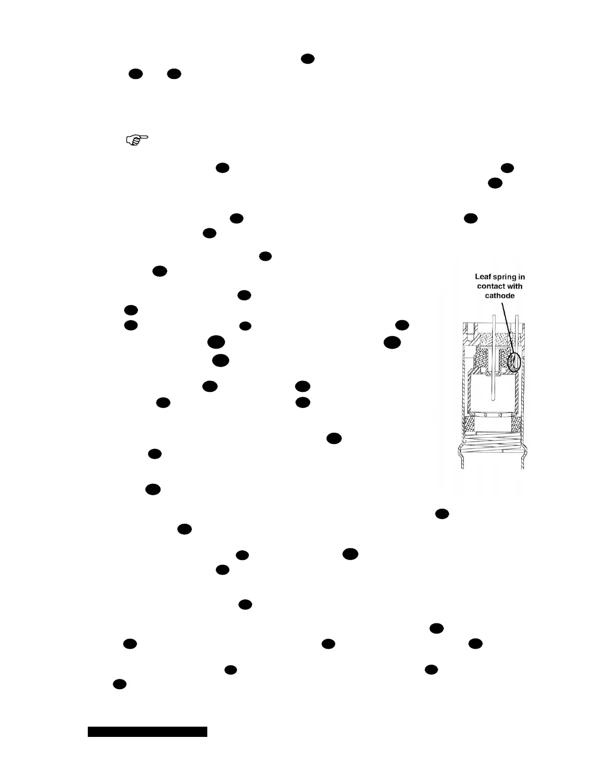
4. Check that the leaf spring
1
will contact the base of the cathode
6
, as shown to the right. If not, remove the small ceramic spacer
7
and the ground shield
8
, and gently bend the leaf spring
1
towards the anode
10
and then replace the ground shield
8
and ceramic spacer
7
.
5. Slide the cathode
6
, the grid washer
5
, and the large ceramic
spacer
4
into place. The grid washer
5
has a concave shape.
Refer to the figures to see its installation orientation.
6. Insert the small end of the compression spring
3
into the sensor
body
9
.
7. Using your thumbs, push the larger end of the spring into the sensor
body
9
until it is contained within the tube's inside diameter.
8. Using the smooth-jaw, needle-nose pliers, work the compression spring
3
down into the
sensor body
9
until it is fully seated in the formed groove.
9. Inspect the ground shield
8
and the grid washer
5
to verify they are centered with
respect to the anode
10
.
10. If adjustment is needed, gently reposition the grid washer/cathode assembly, taking care not
to scratch the grid washer
5
.
It is recommended that the resistance between the ion current feedthrough pin
13
and the grid
washer
5
be measured to verify that the leaf spring
1
is in contact with the cathode
6
. The
measurement should indicate a short circuit between them. There should be an open circuit between
the ion current feedthrough pin
13
and both the high voltage feedthrough pin
2
and the sensor
body
9
.
 Loading...


