MKS 937B Operation Manual
30
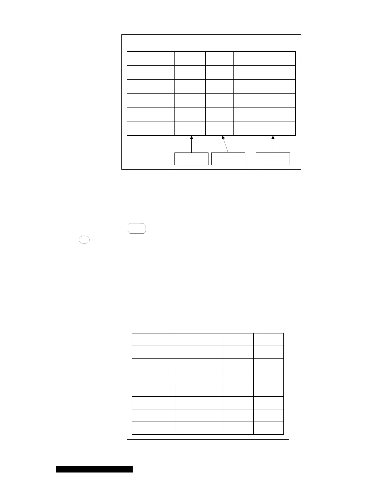
Firmware Version and SN
Slot A 0000000009CC 0.01
Slot B 0000000002CM 0.04
Slot C 0000000008PR 0.02
Analog IO 0000000004AIO 0.01
Comm 0000000007Com 0.03
Main 0000000028Main 0.01
Detected
board
Firmware
Version
Serial
Number
Figure 6-5 System firmware and serial number information displayed on 937B LCD screen.
11. Set DAC Parameter
The Log/Linear analog output for each individual channel, as well as the combination analog
output can be accessed by adjusting the DAC parameter. To view or modify the DAC
parameter, press
System
Setup
and move the cursor to Set DAC Parameter. Select ON and press
Enter
on the System Setup screen and the parameters used in determining the DAC
logarithmic/linear analog output are displayed. These parameters can be modified, as shown
in Figure 6-6.
Both slope A and offset B must be selected when a logarithmic linear equation is used. The
slope A is the voltage per decade, and the offset B is the desired voltage when the measured
pressure is equal to 1 torr. The valid range for A is from 0.5 to 5, while the valid range for B is
from –20 to 20 V. The default settings are 0.6 and 7.2 for A and B, respectively. If only one
sensor is allowed to be connected to the board (such as HC of single channel CC), only one
equation is displayed (i.e. A1, as shown in Figure 6.6).
Set DAC Parameter
BA
Channel A1 7.20E+06.00E-1
Channel A2
Channel B1
Channel B2
Channel C1
Channel C2
Combined
V=AlogP+B
V=AlogP+B
V=AP
V=AP
V=AlogP+B
V=AlogP+B
Equation
1.00E+2
7.20E+06.00E-1
7.20E+06.00E-1
1.00E+3
7.20E+06.00E-1
Figure 6-6 Setting DAC logarithmic and linear analog output.