MKS 937B Operation Manual
63
The outside of the nipple can get hot and may burn the skin.
7.2.5 Connecting a Hot Cathode Sensor to the 937B Controller
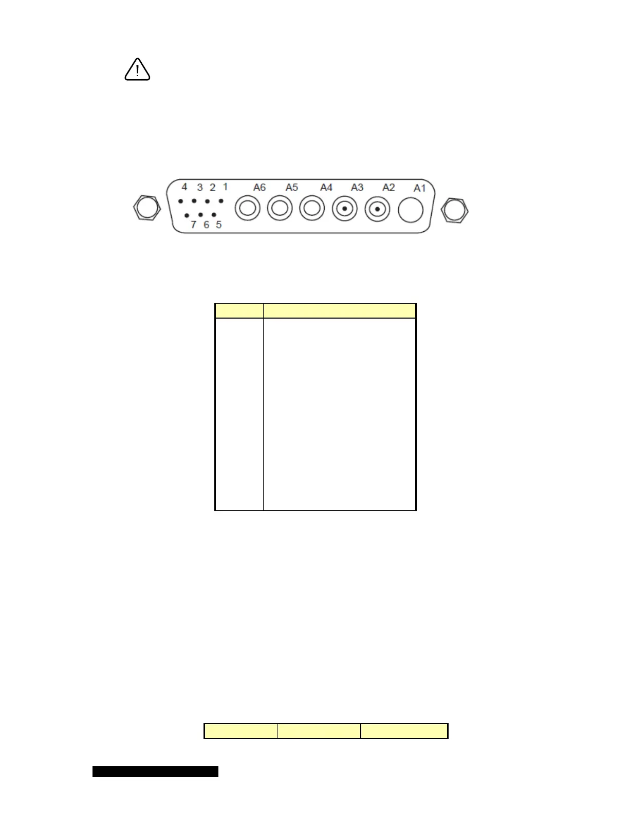
A sensor cable with a 13 pin D-Sub connector (Figure 7-1) is required for operation and this must be
purchased separately from the 937B Controller system.
Figure 7-1 13 pin D-Sub connector on the back of 937B HC board.
The pin out for the hot cathode connector is described in Table 7-1.
Pin # Description
1 Emission current out
2 Emission current in
3 Factory test
4 Factory test
5 Sensor detect
6 Sensor detect common
7 Sensor detect
A1 Not used
A2 Collector current
A3 Grid
A4 Filament 2
A5 Filament common
A6 Filament 1
Table 7-1 Hot cathode connector pin out.
Pins 5, 6, and 7 are used for sensor identification. Therefore, cable needs to be selected to enable
the proper operation of the hot cathode sensor. The setting of these pins for different hot cathode
sensors is described in Table 7-2.
Figures 7-2 and 7-3 show the cable diagrams for Low Power Nude gauge and mini BA gauge,
respectively.
Since much high power is required to operate hot cathode gauge, especially, during degas process,
the maximum allowed cable length of a hot cathode is restricted to less than 50 ft (15 m), which is
significantly shorter than that is allowed for operating a cold cathode sensor.
Sensor Pin 5 Pin 7