MKS 937B Operation Manual
35
When a capacitance manometer is zeroed, a U will be displayed under the gauge type
indicator (CM) to indicate that this manometer has been user calibrated.
You cannot use another capacitance manometer to autozero a capacitance manometer since
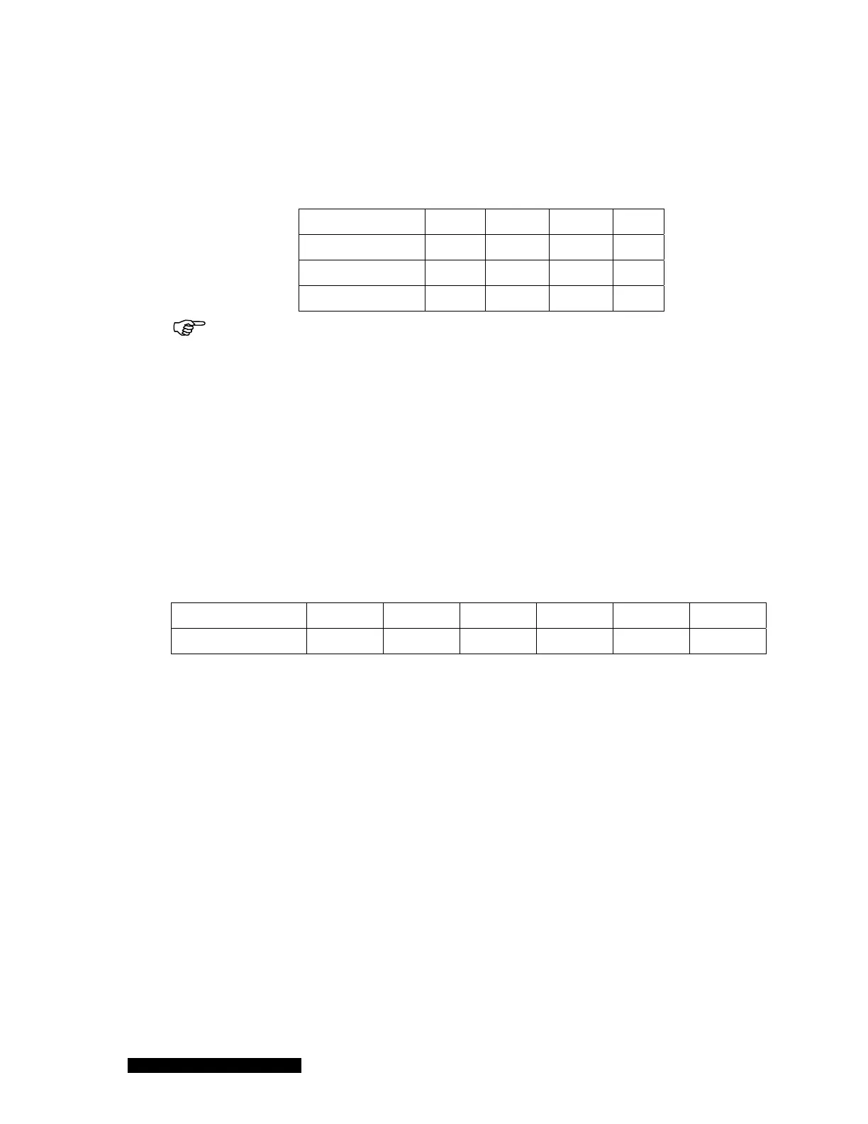
the range cannot be auto-detected. Table 7-1 shows the valid gauges that can be used for
autozeroing manometers that have different full-scale ranges.
Table 6-1 Valid gauges for autozeroing capacitance manometers of different ranges.
Full scale of CM CP PR CC HC
1000 Torr
Yes Yes Yes Yes
100 Torr No Yes Yes Yes
20 Torr
No No Yes Yes
The capacitance manometer and the reference auto-zero sensor must be
connected to the same chamber at all times.
6. Manual Zero
The default setting for the Manual Zero function is NO. When it is set to YES the manometer
can be manually zeroed. To do so, the system pressure must be less than 10
-5
xP
FS
(5
decades less then the full scale). The Manual Zero function will abort if the overall offset is
great than 5% of the full scale.
When a capacitance manometer has been manually zeroed, a U will be displayed under the
gauge type indicator (CM) to indicate that this manometer is user calibrated.
7. Relay
Relays for each capacitance manometer channel are preset (2 per channel), as shown
below. These values are auto-detected.
Sensor location A1 A2 B1 B2 C1 C2
Relay assigned 1 & 2 3 & 4 5 & 6 7 & 8 9 &10 11 & 12
8. Enable
There are three ways to enable a relay:
a. SET: forces the relay to stay in the activated state (closed) regardless of pressure
and setpoint values
b. CLEAR: forces the relay to stay in the deactivated state (open) regardless of
pressure and setpoint values.
c. ENABLE: the relay status is determined by the pressure, setpoint value, and
direction.
9. DIR
DIR determines when the relay is activated. If ABOVE is selected, the relay will be activated
when the pressure is above the setpoint (higher than the setpoint pressure). If BELOW is
selected, the relay will be activated when the pressure is below (less than) the setpoint. The
default setting for DIR is BELOW.
Figure 8-1 provides a more a detailed description of the DIR setting.
10. SET SP