MKS 937B Operation Manual
24
BR
1.003E+1
2.103E+3
1.005E+1
9.982E+0
BR
FC
N2
FC
N2
A1
A2
B1
B2
C1
C2
125%
SP11
SP12
SP9
SP10
SP5
SP6
SP7
SP8
SP1
SP2
SP3
SP4
M
F
C
R
A
T
I
O
A
Torr
REMOTE
1.007E+2
FC
N2
2.506E+0
FC
N2
9
10
8
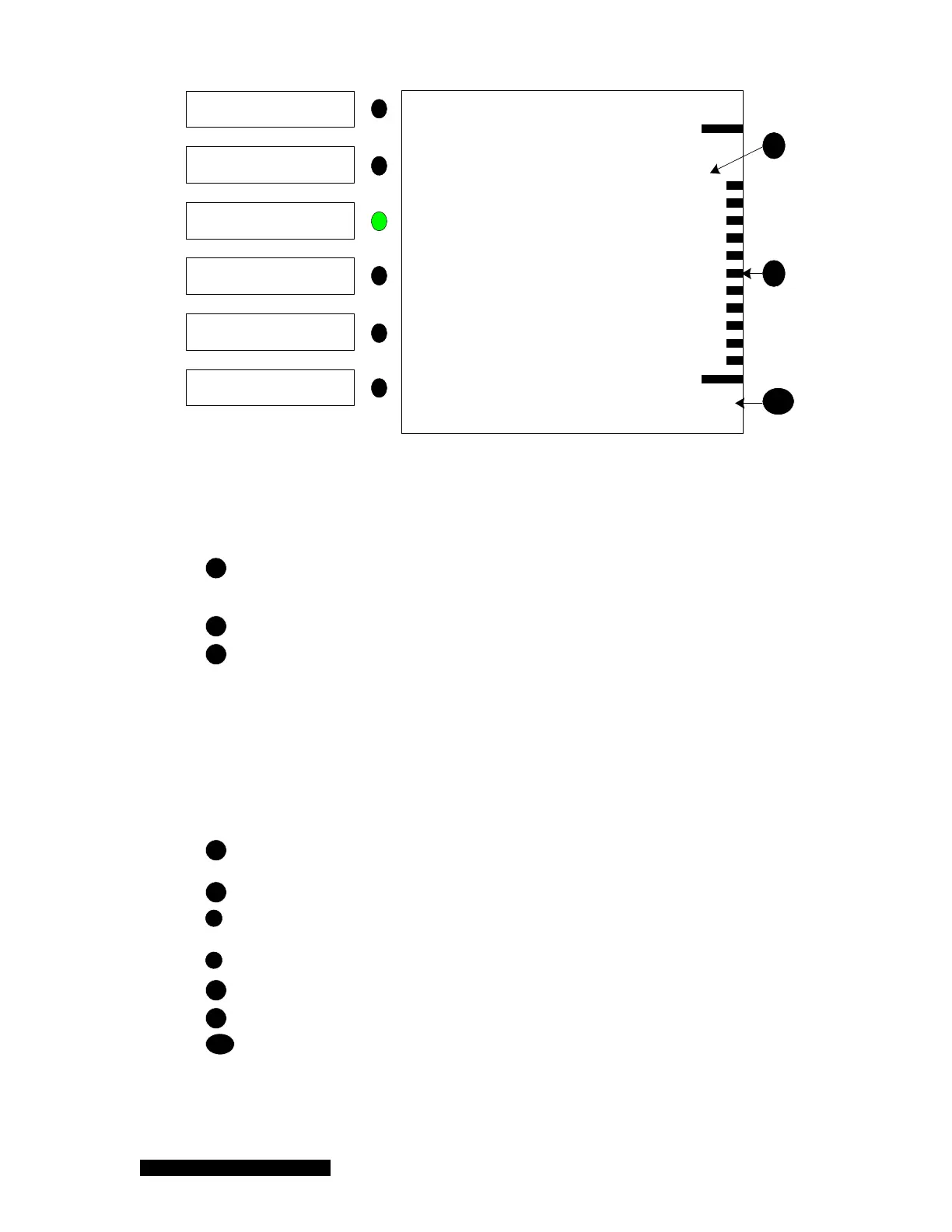
(b)
Figure 6-1 Standard 937B LCD front panel display for pressure measurement (a) Leak
detection mode; (b) MFC Ratio or Valve control mode.
1
Type of sensor detected (CC = cold cathode, HC = hot cathode, PR = Pirani, CP =
convection Pirani, CM = Capacitance manometer, FC = Mass flow controller, N2, Ar,
He = Gas type, U = User Calibrated)
2
Pressure/flow readings for all of the detected sensors.
3
Control information which includes:
For a cold cathode gauge, C1 Ctrl means the cold cathode gauge is
controlled by channel C1.
For a hot cathode gauge, C2 Ctrl means the hot cathode gauge is controlled
by channel C2. F2 means filament 2 is the active filament, DG means the
gauge is degassing.
For PR/CP/CM, A1 AZ means the PR/CP/CM will be auto-zeroed by the
gauge on Channel A1 (typically, an ion gauge).
4
Relay status: displayed channel = activated relay; ---- = enabled, but, not activated
relay; blank = relay is not yet set.
5
Pressure units (Torr, Pascal, mBar, Microns)
6
Leak checking status; displayed only when the leak check is activated. When active,
the color for the pressure reading of the corresponding sensor turns to blue.
7
Front screen is locked when REMOTE is displayed
8
Control mode: MFC Ratio A, MFC Ratio M, Valve Position
9
Control parameter, either the ratio value or the valve position
10
Digital indication of the control parameter

 Loading...


