MKS 937B Operation Manual
96
10 937A Emulated Operation and RS232/485
Serial Communication Commands
10.1 Operating the 937B controller in 937A emulated operation
mode
The 937B controller can be operated in 937A emulated operation mode. In this mode, the user can
employ existing cables and connectors to obtain identical relay control and analog output. However,
since significantly more relays (12 relays for the 937B vs. 5 relays for the 937A) and sensors can be
connected to the 937B controller, different connectors are used on the 937B, and adaptors are
required for the smooth transition.
When setting the 937B to the 937A operation mode, a cold cathode card has to be
inserted into slot A (equivalent to CC in the 937A) to ensure that the communications
commands work properly.
When setting the 937B to the 937A operation mode, only 5 relay channels can be
controlled via the serial communication commands. Channels 1,2,3,4 and 5 in the 937A
serial commands correspond to Channels 1, 5,7,9 and 11, respectively, in the 937B.
These relays are highlighted in blue on the Channel Setup screen. See the details in
Table 10-1 for adapting the 937A’s 15pin Dsub connector to the new 937B 25pin relay
output connector.
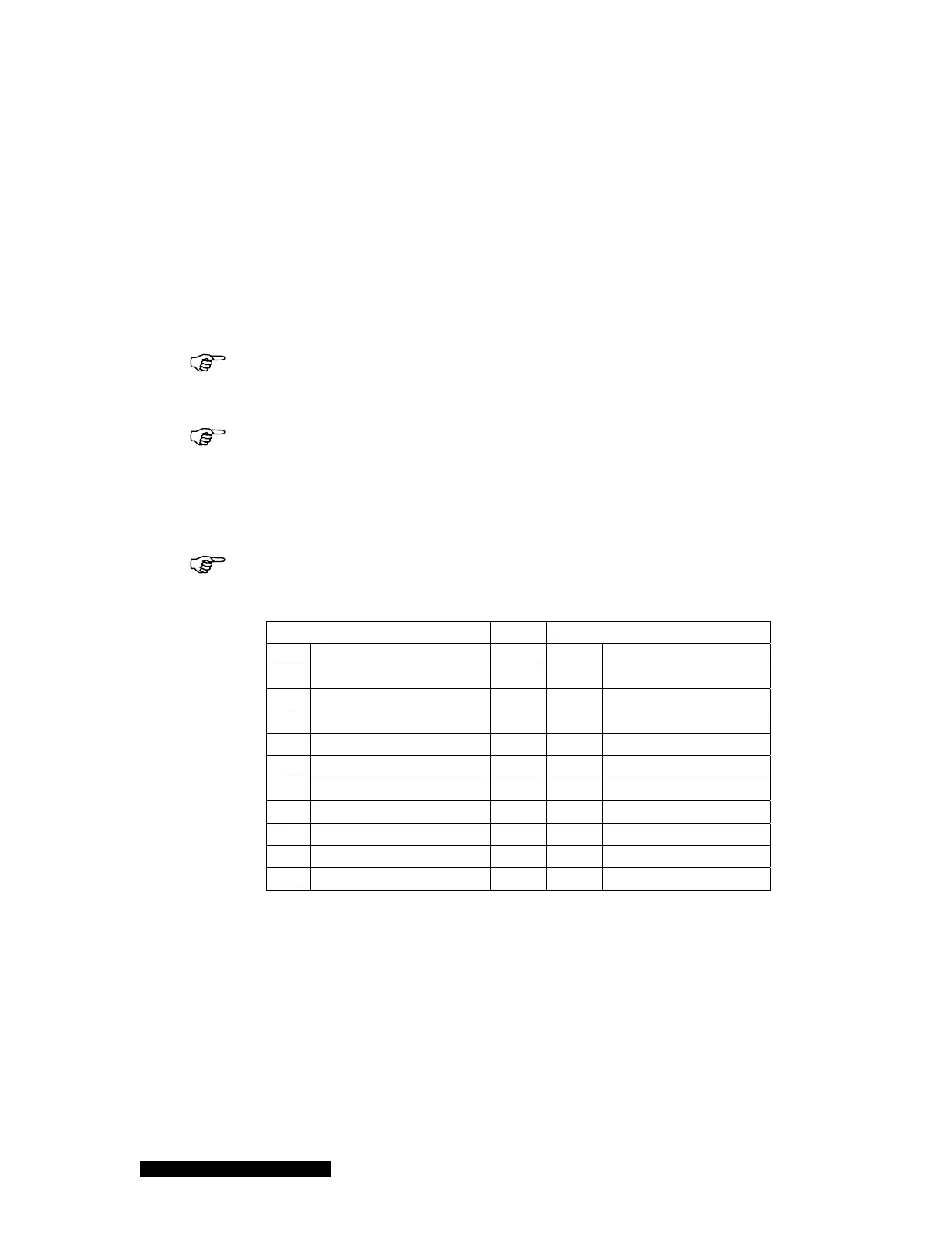
With the 937B, there is no normally closed relay connection available!
937B (25 pin Dsub)
937A (15 pin Dsub)
Pin Description Pin Description
1 Relay 1 NO
2 CC NO
2 Relay 1 Common
9 CC Common
9 Relay 5 NO
10 A1 NO
10 Relay 5 Common
11 A1 Common
14 Relay 7 NO
12 A2 NO
15 Relay 7 Common
5 A2 Common
18 Relay 9 NO
13 B1 NO
19 Relay 9 Common
14 B1 Common
22 Relay 11 NO
7 B2 NO
23 Relay 11 Common
15 B2 Common
Table 10-1 Description of pin assignment for adapting 937A 15 pin connector to 937B 25 pin
connector for relay output.
An adaptor is required to adapt the 937A Controller 25pin analog output accessory cable to the 937B
37pin Dsub connector. Detailed descriptions of the pin assignment for the adaptor are shown in Table
10-2.