MKS 937B Operation Manual
71
control and should be avoided. The hysteresis setting must therefore be higher than the
setpoint.
Thus, when direction is set to ABOVE, the hysteresis must be lower than the setpoint, while
when the direction is set to BELOW, the hysteresis must be higher than the setpoint.
When Direction is changed in the 937B controller, a default offset value (about 10%) is given
to the hysteresis to avoid above-mentioned problem. Depending on the application, this value
may need to be optimized by the user.
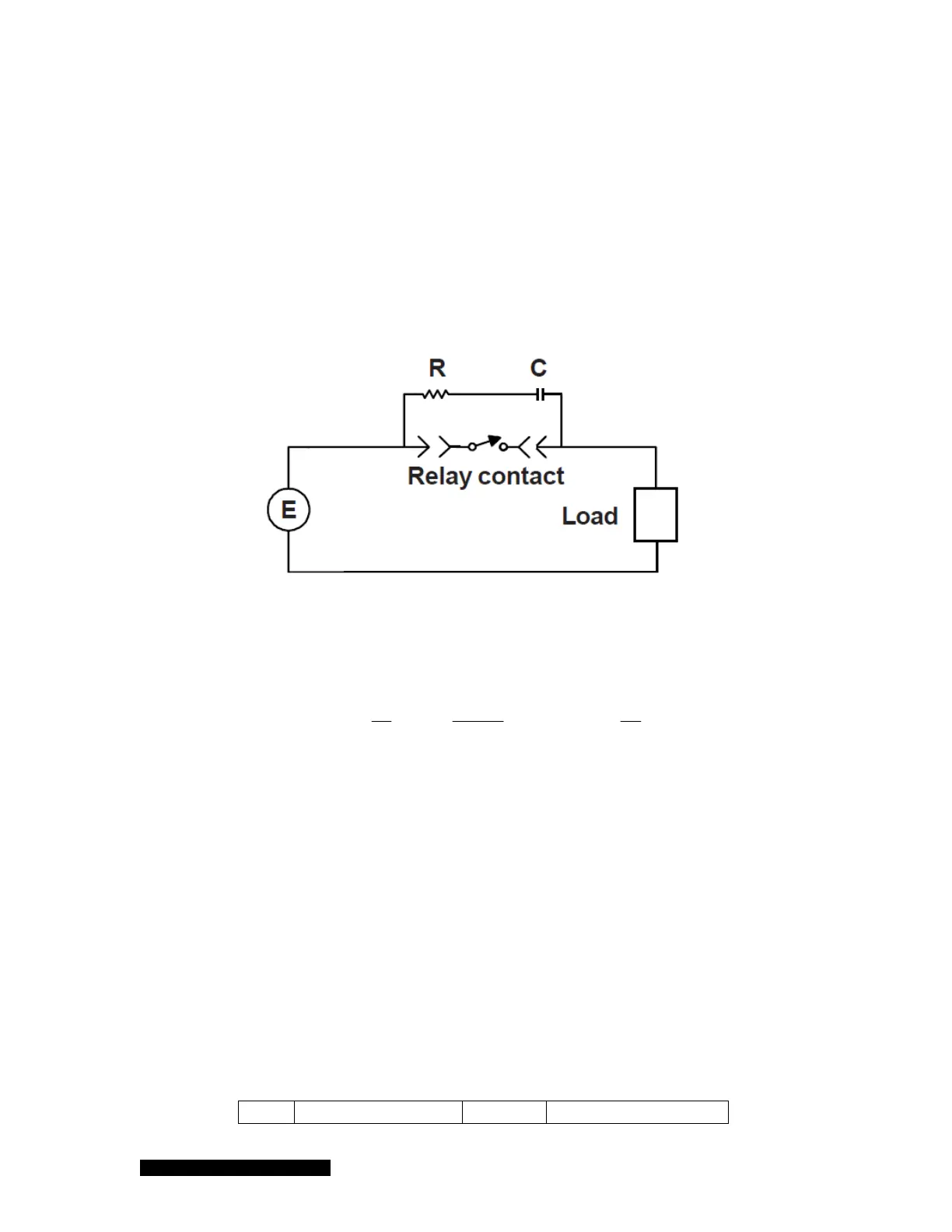
8.1.3 Relay Inductive Loads and Arc Suppression
If the set point relay is used to switch inductive loads, e.g., solenoids, relays, transformers, etc.,
arcing of the relay contacts may interfere with the controller operation or reduce relay contact life. An
arc suppression network, shown schematically in Figure 8-2, is therefore recommended.
Figure 8-2 The relay arc suppression network.
The values of the capacitance C and the resistance R are calculated using the equations:
E
aand
I
E
R
I
C
a
50
1
10
;
10
2
where C is in F, R is in , I is the DC or AC
peak
load current in amperes, E is the DC or AC
peak
source voltage in volts. C
min
= 0.001F and R
min
= 0.5 .
8.2 Connecting the 937B Analog Output
Analog outputs are output via the 37-pin connector on the back of the AIO module. These analog
signals can be used to for a variety of process control and other purposes. In particular, a combined
logarithmic output capability allows two sensor outputs to be combined, providing the controller with a
much wider pressure measurement range.
Analog output signals, which can be sent to a data acquisition system, are available for each sensor.
These signals can be accessed from the 37 pin D-sub female connector on the back of the controller.
They include buffered, logarithmic, and combination logarithmic output. Buffered and logarithmic
analog outputs are simultaneously available from all sensors. The detailed assignment for these pins
is described in Table 8-2.
Pin Description Pin Description