MKS 937B Operation Manual
33
Range
Factory Default
Manual Zero
1000
NO
Auto Zero
NO
A1
Relay Relay n
NO
YES
Enable
DIR
SET SP
Hyst
OFF
BELOW
1.00E+01
1.50E+01
0.02 to 20,000
NA
Ion gauge Channel
Message
Display 2 Relays, Ch# auto detected
ON
OFF
ABOVE
BELOW
Display warning message
CM
1% to 95% of its full scale
Channel
Setup
MFC
Scale Factor
Zero
FD
1.00
NO
FlowRate SP
NO
2.00E+2
Relay Relay n
NO
YES
Enable
DIR
SET SP
Hyst
OFF
BELOW
1.00E+01
1.50E+01
0.1 to 10
Open
Message
Display 2 Relays, Ch# auto detected
ON
OFF
ABOVE
BELOW
Display warning message
1% to 95% of its full scale
Nominal Range 1.00E+3
0.1 to 1.00E+6
Range 1.00E+3
OP Mode Setpoint
Display only
Close
Setpoint
PID Ctrl
RatioM
RatioA
PID Ctrl OFF
R1 to R8, NA
Recipe R1
Edit OFF
0 to Nominal Range
ON
OFF
ON
OFF
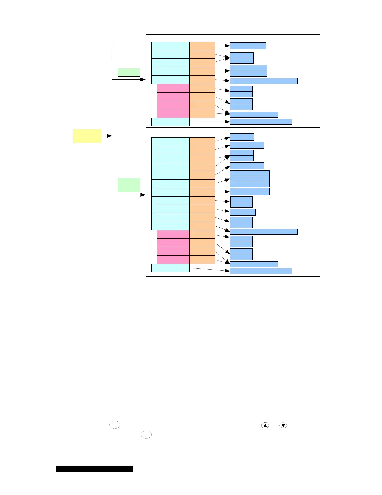
Figure 6-7 937B Channel Setup setting parameters, their default values and ranges.
6.5.2 Setup for a Capacitance Manometer
A capacitance manometer board present in the 937B controller will be automatically detected and
displayed on power-up. At the same time, the connection of the capacitance manometer to the control
board will be checked. If no capacitance manometer is connected, MISCONN will be displayed.
Refer to Figure 6-8 in setting up a capacitance manometer.
1. CM Type
Only ABS (absolute) capacitance manometer is available.
2. Input Voltage
The Input Voltage (for the 937B controller) is same as the maximum analog output voltage of
the capacitance manometer. To select the correct value, move the cursor to the Input Voltage
box, press
Enter
, and this parameter will be highlighted. Use either or to select the
correct voltage. Press
Enter
to save the correct setting. The valid input voltage ranges for a
capacitance manometer are 10, 5, and 1 V. The default value is 10 V.